
 Zhejiang Hongyan Electric Co., Ltd.
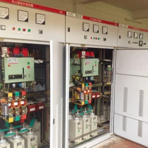
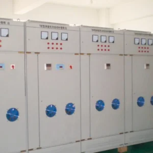
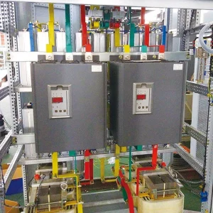
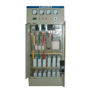
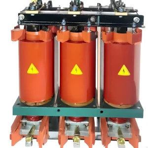
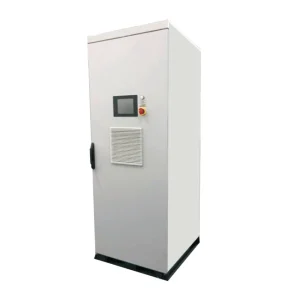
Filter reactor replacement requires matching the complete reactor-capacitor branch, not simply finding a coil with the same kvar label or mounting holes. Confirm the original inductance, capacitor connection and capacitance, tuning objective, operating frequency, current spectrum, insulation requirements and thermal protection. Then establish why the original reactor failed before energizing a replacement. This guide addresses replacement specification and return-to-service evidence. It does not provide live working instructions, authorize changing protection settings or suggest that an interchangeable-looking component is electrically equivalent.
Identify the branch before ordering a component
Begin with the as-built circuit and the original equipment schedule. Determine whether the reactor belongs to a tuned harmonic filter, a detuned compensation step, an inrush-limiting arrangement or another circuit. Similar external construction does not establish the same function. A replacement intended for one duty can change the behavior of a branch designed for another.
Record the original nameplate, serial number, terminals, connections and any taps. Obtain the cabinet manufacturer's component schedule where possible. If records disagree with the installed unit, resolve that discrepancy before ordering. Photographs help identify construction and damage, but they cannot establish inductance, insulation condition or harmonic-current capability.
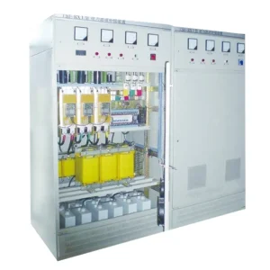
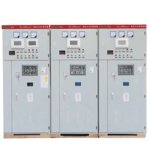
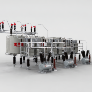
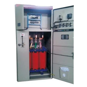
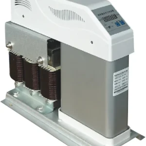
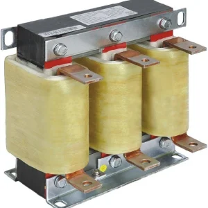
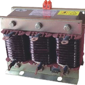
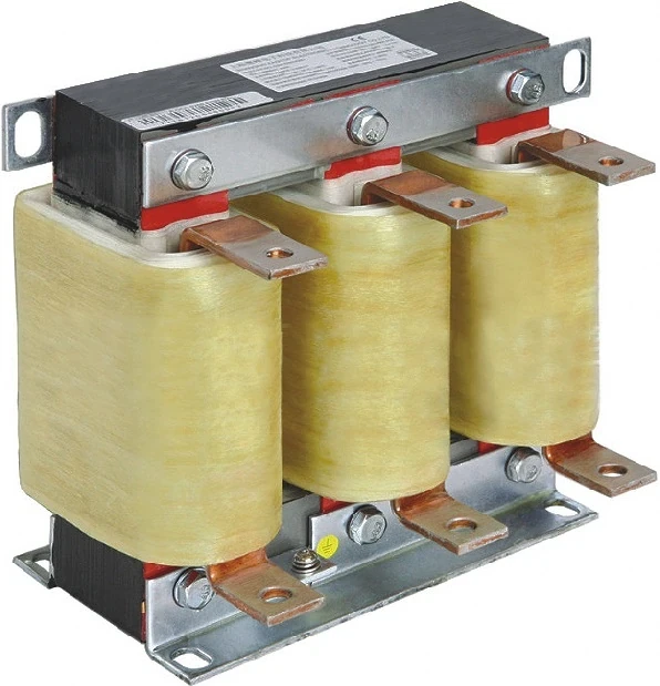
The CHYN LKSG filter reactor family is described for use in LC harmonic-filter branches. A family description is a starting point for an enquiry. It is not evidence that every model can replace a particular detuned reactor or that an existing capacitor bank can remain unchanged.
Match electrical values rather than shorthand labels
List system voltage and frequency, connection arrangement, inductance per phase, tolerance and the conditions under which inductance is specified. Request the manufacturer's declared current duty, including relevant harmonic components. Distinguish fundamental current, total RMS current and short-time withstand. The same fundamental current can coexist with different harmonic heating requirements.
A kvar value may refer to the associated capacitor output, a branch output at a defined voltage or another manufacturer's naming convention. Ask what it means on both the original and proposed devices. Do not translate one catalogue label into another without checking the electrical values and branch drawing.
Insulation requirements also need context: operating voltage, insulation coordination, terminal clearances and the cabinet environment all matter. Identify the applicable project requirements with the equipment designer. Reusing the original mounting position does not establish that the new unit has suitable insulation or acceptable clearances to adjacent components.
Recalculate the branch with the actual capacitors
For an ideal series LC branch, resonance frequency is fr = 1/(2π√LC), where L is inductance in henries and C is the corresponding branch capacitance in farads. The values must represent the same phase equivalent and connection. Line-to-line readings on an assembled three-phase bank cannot be inserted into the formula without the appropriate circuit conversion.
As a mathematical sensitivity example, if capacitance falls to 90% of its original value while inductance stays unchanged, resonance frequency becomes 1/√0.90, or about 1.054 times its original value. This illustrates a roughly 5.4% upward shift. It is not a permitted maintenance tolerance or a recommendation to retain a degraded capacitor.
Check each phase and branch against the original design limits. A new reactor paired with aged or incorrectly replaced capacitors may not restore the intended response. Conversely, replacing capacitors without checking reactor values can change a filter that previously worked. Approve the combination as an assembly, including component tolerances and credible operating conditions.
Find the failure mechanism
Inspect the available trip history and operating records before treating the event as ordinary wear. Was the reactor temperature high during a particular process? Did a capacitor fuse operate first? Were ventilation filters blocked, fans unavailable or supply harmonics different after new drives were installed? Preserve the sequence where it can be established.
Differentiate an electrical overload from a cooling or connection problem. A loose connection can create local heating without representing the winding's average thermal duty. A damaged temperature sensor can also create confusing indications. Investigation and testing should be performed by qualified personnel under the approved isolation and stored-energy procedure.
For a complementary fault investigation, see detuned reactor overheating checks. The purpose here is to carry the confirmed cause into the replacement specification, so the next unit is not exposed to an unchanged problem.
Compare the complete replacement proposal
This table is a decision checklist, not a specification of numerical limits. Obtain acceptance values from the approved design and selected component documentation. Any proposed deviation should be visible to the cabinet designer and owner before installation.
| Replacement item | Evidence needed | Reason to resolve it |
|---|---|---|
| Inductance and tolerance | Declared per-phase values and test conditions | Maintains the intended LC relationship |
| Current duty | Fundamental and harmonic loading basis | Avoids treating RMS current alone as a complete thermal assessment |
| Capacitor match | Connection, capacitance and approved voltage duty | Checks the actual branch combination |
| Thermal protection | Sensor type, contact action and trip circuit drawing | Preserves the intended protective response |
| Mechanical installation | Dimensions, mass, orientation, clearances and ventilation | Confirms cabinet compatibility |
| Documentation | Revised bill of materials and test report | Keeps future maintenance traceable |
Review network changes since the original installation
The replacement component returns to today's electrical network, which may differ from the network used in the original study. List additional drives, rectifiers, solar inverters and capacitor banks. Include transformer replacements, bus ties and changes to standby supply operation. Record which combinations are permitted rather than assuming that the normal utility configuration covers every case.
The ABS guidance on electrical harmonics explains harmonic sources, system interactions and mitigation considerations in its marine context. Its discussion supports reviewing the network and filter together; its application context is not an industrial-site compliance certificate.
Request an updated frequency or harmonic assessment when changed inputs could affect branch duty. A larger reactor or a different tuning percentage should be treated as a design change, not an automatic improvement. The proposed assembly still needs to meet the actual compensation and filtering objective.
Preserve thermal and mechanical protection
Check cooling-air paths with the replacement dimensions, connection positions and cable routing. A unit that physically fits can obstruct another component's ventilation. Confirm that surrounding surfaces, cable insulation and enclosure materials remain within their specified conditions during representative operation.
Verify the temperature protection circuit against the approved drawing, including the response to sensor wiring faults where the design provides it. Never bridge a thermal contact merely to complete commissioning. If a replacement uses a different sensor interface, obtain an approved circuit modification rather than adapting it informally in the cabinet.
Maintain required clearances and support for mass and vibration. Confirm terminal material, conductor preparation and tightening instructions with the selected equipment documentation. These details belong in the installation work package and inspection record; a generic torque value from another product is unsuitable.
Plan return-to-service verification
Before energization, complete the manufacturer's prescribed inspection and tests under approved isolation procedures. Confirm phase identification, protective circuits, connection arrangement and documentation. Record measured component values with the test method and instrument information. Do not perform high-voltage or insulation tests through connected electronics unless the manufacturer explicitly permits the method.
During authorized operation, capture branch current, voltage, relevant harmonic components and temperature behavior with the actual load and switching state documented. Compare against the approved acceptance values. A short no-load energization cannot establish sustained thermal suitability under production conditions.
IEEE's capacitor-bank topic overview describes switching and resonance considerations that also matter when maintaining associated reactor branches. For the wider network issue, use passive harmonic filter resonance assessment. For the basic percentage concept, see the meaning of a 7 percent detuned reactor; that percentage alone remains insufficient for a replacement order.
The educational lecture below explains passive filter principles. Use it to understand why component matching matters, while relying on the approved design and component documentation for actual replacement work.
Watch the educational lecture on YouTube.
Build a useful spare-parts record
After acceptance, update the branch drawing, bill of materials and maintenance record with the installed unit's identity, approved substitutions, capacitor measurements and protection settings. Keep the original failure report and the final operating trace. If another branch later fails, these records help distinguish a repeated network problem from an isolated component fault.
When keeping a spare, record storage conditions and the inspection required before use. Retain its factory documents with the approved branch reference, rather than identifying it only by cabinet location. If a spare is moved between plants, reassess the electrical duty and environmental conditions at the destination. A physically identical cabinet can contain a different capacitor combination or operate from a different source. Keep substituted parts quarantined until their application has been approved, and mark obsolete drawings so a later maintenance team does not order the original unsuitable combination again.
Frequently asked questions
Can the same kvar rating establish equivalence?
No. Confirm what the rating describes, then compare inductance, capacitor matching, frequency, harmonic duty, insulation and thermal requirements.
Must capacitors always be replaced with the reactor?
Not automatically. Assess their condition and measured values against the approved branch design. Replace or retain them only on that documented basis.
Can a different tuning percentage improve protection?
It changes the branch design and may alter current, voltage and network interactions. Obtain a design review before approving the substitution.
What proves a successful replacement?
Use approved component and circuit checks plus representative operating measurements, with the original failure cause addressed and the installed configuration recorded.