
 Zhejiang Hongyan Electric Co., Ltd.
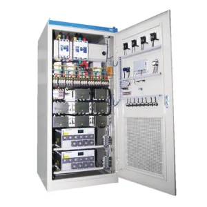
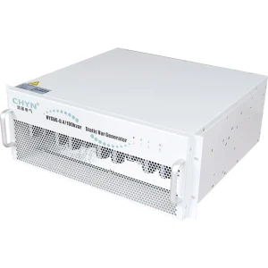

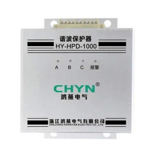
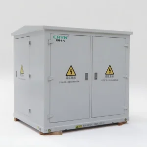
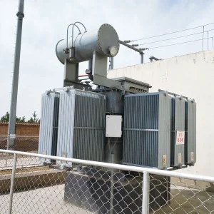
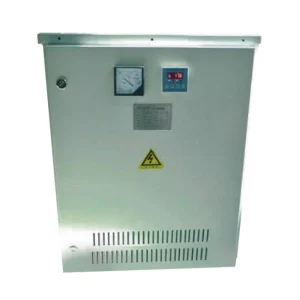
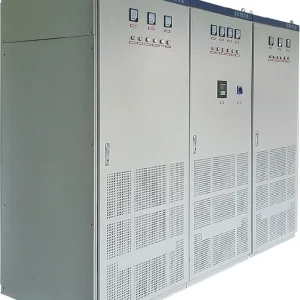
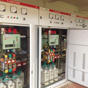
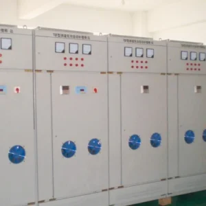
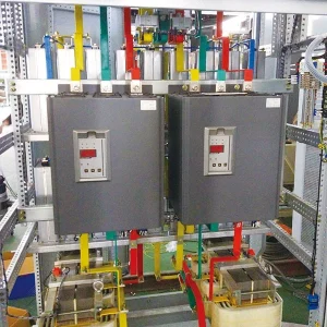
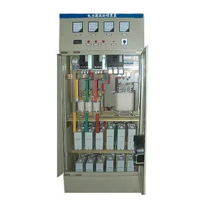
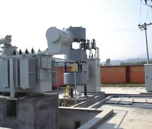
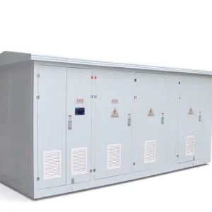
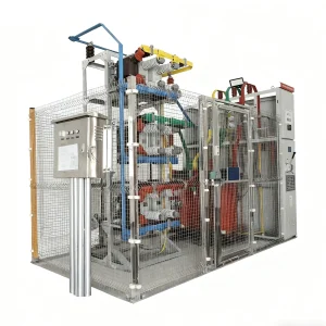
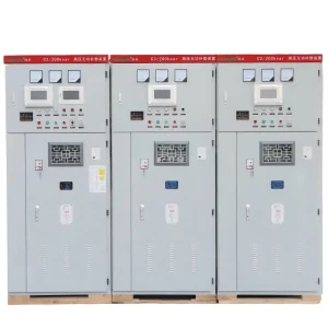
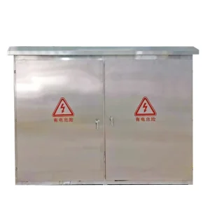
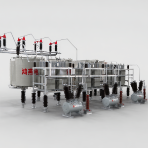
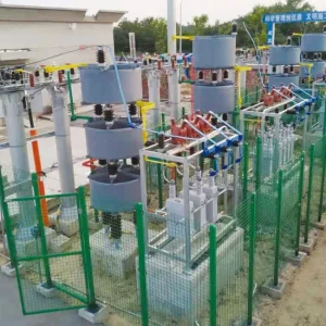
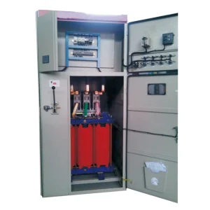
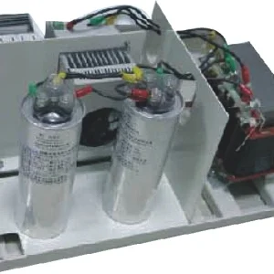
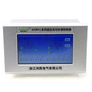
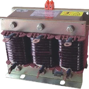
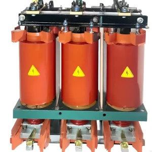
Medium voltage capacitor bank protection coordination starts with the actual bank connection, capacitor arrangement and failure consequences, then assigns selective alarm and trip duties to the fuses, relays and switching devices. A single overcurrent setting cannot cover every internal element failure, switching event and external system fault. Before approving settings, obtain the as-built series-parallel arrangement, capacitor and fuse data, instrument-transformer details, fault study and switching-duty assessment. The acceptance result should show which device acts for each credible condition, how quickly the fault clears, and why normal switching or an external disturbance does not produce an unnecessary bank trip.
Define the bank before discussing relay settings
Two capacitor banks with the same voltage and kvar rating can require different protection arrangements. Grounded wye, ungrounded wye, double-wye and other configurations produce different measurable signals after a failure. Internal fuses, external fuses and fuseless construction also change what happens when an element or unit fails. Identify the exact construction rather than selecting settings from the rating plate alone.
The IEEE project page for the shunt capacitor bank protection guide identifies protection of shunt and filter capacitor banks as its scope. That public page is a scope reference, not the complete guide or a source of numerical settings. Check the applicable published edition and the project's governing requirements before applying any standard-based calculation.
Obtain a drawing that lists series groups, parallel units, internal construction where required, neutral treatment and instrument-transformer locations. Mark every switching device and fuse. A copied drawing from a previous project may conceal a different number of parallel units or a different CT boundary, changing both sensitivity and the consequences of a failed component.
Separate internal failure detection from system protection
Unbalance functions can detect changes caused by failed elements or units, depending on the selected arrangement. Overcurrent and voltage functions address other conditions, including major faults or abnormal system operation. Each function needs a defined purpose. Adding many enabled functions without understanding their interaction can create duplicate trips and unexplained outages.
The University of Idaho dissertation Capacitor Bank Unbalance Protection Enhancements discusses how component failures affect healthy units and how some failure patterns reduce the net unbalance signal. This research highlights a practical limitation: a small measured unbalance cannot prove that every internal element is healthy.
For the broader detection principles, see the site's capacitor bank unbalance protection guide. The present coordination review focuses on assigning actions and timing across devices. It should use the same bank model as the unbalance calculation, but it must also include fault interruption, external disturbances and the final trip circuit.
The parent high-voltage capacitor bank design guide provides the wider equipment-planning context. Keep the protection model tied to the approved design so later changes to the capacitor arrangement also trigger a settings review.
Build a condition-and-action matrix
| Condition | Protection question | Coordination evidence |
|---|---|---|
| Initial element or unit failure | Can the selected measurement detect the change? | Failure model, expected signal and approved alarm/trip decision |
| Severe internal bank fault | Which device clears the fault before damage escalates? | Fault-current study, equipment limits and clearing-time assessment |
| Normal capacitor energization | Will transient current cause an unwanted operation? | Switching study and applicable relay/fuse response |
| External feeder or bus fault | Should the bank remain connected, trip or be blocked? | System protection philosophy and adjacent-device coordination |
| Lost voltage measurement | Can a failed signal imitate an internal problem? | VT supervision logic and tested alarm/trip behavior |
| Breaker fails after a trip command | What backup action removes the fault? | Approved breaker-failure scheme and end-to-end test |
This matrix is a project review framework, not a universal relay configuration. Each row needs its own engineering justification. Add conditions specific to the installation, such as connected filter reactors, multiple adjacent banks, alternative supply arrangements or a bus coupler that changes fault levels.
Coordinate fuses with the bank's damage consequences
Where fuses are used, obtain the precise fuse type and manufacturer characteristics rather than a generic ampere rating. Evaluate the relevant operating and clearing characteristics against the bank's failure cases and normal switching duty. The fuse must interrupt the duty for which it is selected; a current rating alone does not establish that capability.
After a fuse removes a unit or an internal element, the voltage distribution within the remaining arrangement can change. Determine the resulting stress from the actual circuit model and capacitor data. The relay alarm and trip decisions should follow that consequence assessment. Do not apply a universal rule that every first fuse operation is harmless or that every first operation requires the same response.
Keep the fuse and relay assumptions consistent. If one calculation uses a different series-group count or assumes a different failure mechanism, the plotted timing relationship can look coordinated while describing an impossible combination of conditions. Record the source of each curve and all conversions between primary and secondary quantities.
Assess switching and external faults separately
Capacitor energization produces a transient whose duty depends on the source, bank arrangement and nearby energized capacitance. The normal operating current does not represent the entire switching duty. A back-to-back operation can require a different assessment from energizing an isolated bank, even when both operations use the same breaker.
Use the dedicated back-to-back capacitor switching discussion for the transient context. Coordination should compare the calculated switching condition with the actual relay measurement algorithm, fuse capability and switching-device ratings. Simply adding delay to stop a nuisance trip can leave an internal fault energized for too long.
For external faults, establish the expected contribution from stored bank energy and the behavior of the measuring transformers. Review whether temporary voltage or current asymmetry should be tolerated, blocked or cleared. The appropriate action depends on the utility and plant protection philosophy, not on an assumption that the capacitor bank must always stay online.
Check measurement errors before adding sensitivity
A sensitive setting is useful only when the normal measurement uncertainty is understood. Check CT and VT ratios, polarity, phase mapping, wiring burden and the intended operating range. Establish the healthy bank's baseline signal under representative system conditions. Preserve the raw measurements so commissioning adjustments remain traceable.
Compensation for inherent bank or measurement unbalance must not hide a developing fault. Document when a baseline can be established, who may change it and what checks are required after maintenance. If the capacitor population changes, re-evaluate the calculation and baseline instead of assuming the previous compensation remains valid.
Include signal failure in the logic review. A blown VT fuse, broken input circuit or communications problem can resemble an electrical event to an unguarded function. Test supervision using approved simulation rather than disconnecting live measurement circuits. Current-transformer secondaries require the appropriate safe handling procedure and qualified personnel.
Verify the trip path, lockout and return to service
A relay indication proves that a logic element asserted; it does not prove the bank disconnected. Test the path from the intended protective function through output contacts, control supply and trip coil to the actual switching device. Confirm auxiliary feedback, alarms and remote indications against the as-built drawings.
Define what happens after an unsuccessful opening command. The backup action and its timing belong in the overall station protection study. Also define whether an internal bank trip creates a lockout, who investigates it and what inspection or measurement is required before reset. Automatic control must not repeatedly reclose a bank with an unresolved internal fault.
Return-to-service logic must respect the equipment's residual-voltage and discharge requirements. These requirements are related to, but distinct from, fault clearing. Keep the setting record linked to the ordered capacitor and switching-device documentation so a future replacement does not silently invalidate the sequence.
Request evidence with the compensation system
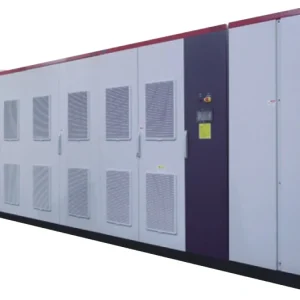
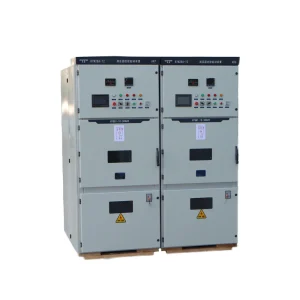
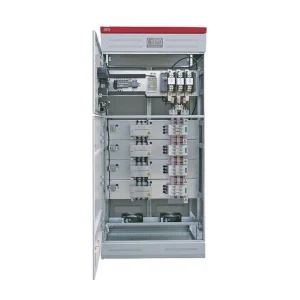
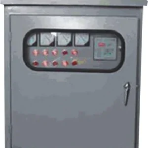
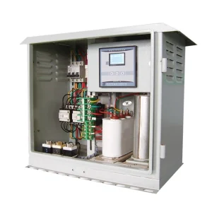
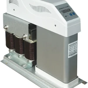
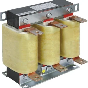
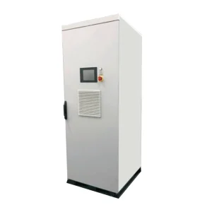
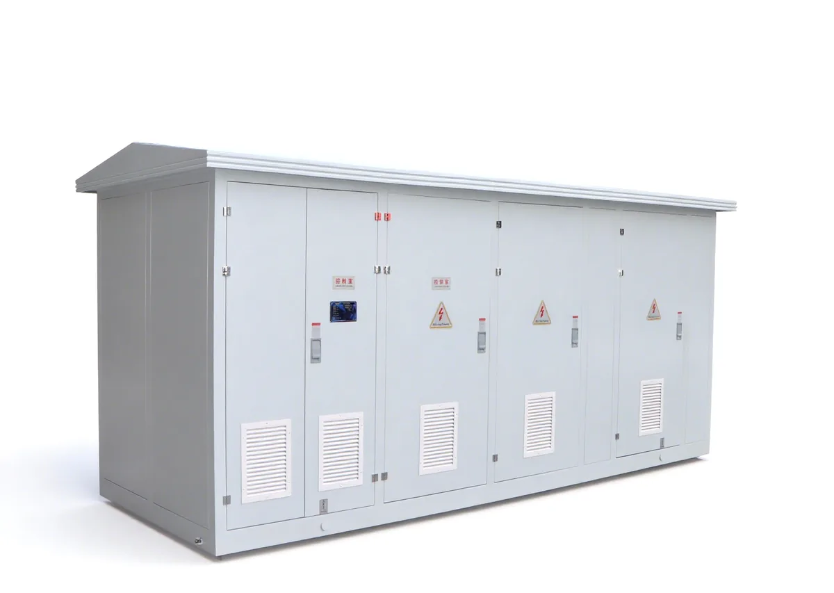
For a project using the CHYN HYTBB outdoor medium- and high-voltage compensation system, specify the actual bank arrangement, required protection functions and interfaces with station control. The public product page provides a starting point for system discussions; it does not certify a particular relay configuration or clearing-time study.
Ask for the final protection calculation, settings file, cause-and-effect matrix, fuse schedule, instrument-transformer details and test plan. Include minimum and maximum source strength, future parallel banks and alternative bus arrangements. A proposal based only on nominal voltage and kvar leaves too many coordination assumptions unresolved.
At acceptance, reconcile the installed hardware with the model before testing. Use secondary injection and approved functional tests to verify pickups, delays, blocking and trip destinations. Record which switching or fault duties were assessed by study rather than physically reproduced. Do not stage an actual capacitor failure to demonstrate a protective function.
Maintain one controlled handover set containing the approved settings, test reports and unresolved limitations. After fuse, capacitor, CT, VT or firmware changes, assess whether the coordination remains valid. A clear change-control record is more useful than a final report that merely says all relays passed without identifying the tested functions.
Learn the protection-zone background
This IIT Roorkee lecture introduces faults, relaying schemes and protection zones. Those concepts explain why a capacitor bank needs a defined relationship with adjacent protection. It is general education, not a source of capacitor-specific settings.

Watch the educational lecture on YouTube.
Frequently asked questions
Can overcurrent protection replace bank unbalance protection?
Do not assume so. The functions respond to different conditions, and some internal element failures may not create enough phase current for timely overcurrent operation. Evaluate the actual bank and failure modes.
Can settings be copied between equal-kvar banks?
Equal ratings do not establish equal construction, measurements or failure consequences. Recalculate for the series-parallel arrangement, connection, capacitor data, fuses and source conditions of the installed bank.
Should a switching trip be fixed by adding delay?
Only after the switching event and the relevant protection response are understood. Additional delay may suppress an unwanted operation while also slowing necessary fault clearing beyond the approved limits.
What proves that coordination is complete?
A consistent calculation, condition-and-action matrix, final settings and verified trip paths are required. Retain test records and clearly state the scenarios assessed by study rather than reproduced on site.