
 Zhejiang Hongyan Electric Co., Ltd.
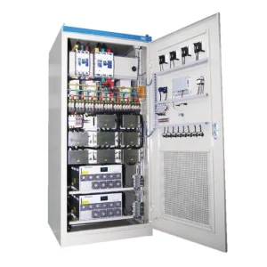
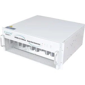
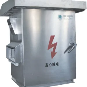
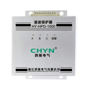
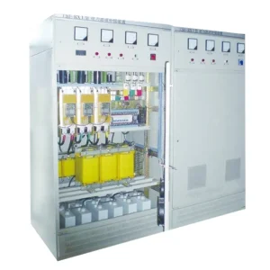
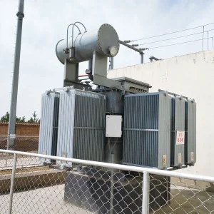
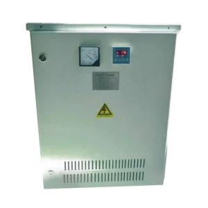
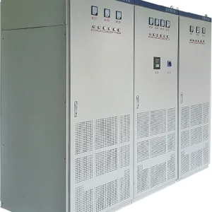
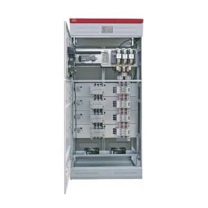
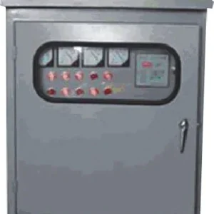
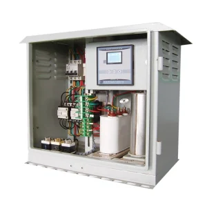
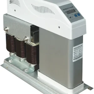
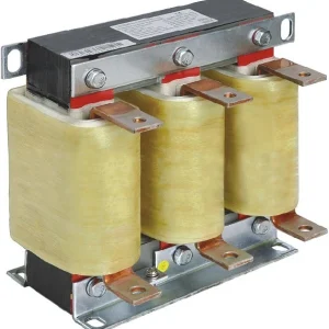
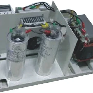
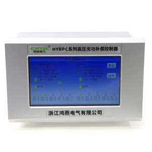
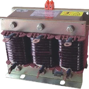
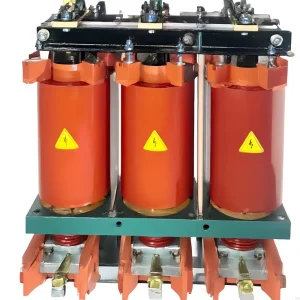
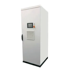
Filter reactor inductance testing is useful only when the measured value can be compared with a reference obtained under defined conditions. Record the winding connection, test frequency, excitation, instrument method and temperature before deciding whether a reactor has changed. A continuity check does not measure inductance, and a handheld meter result does not automatically reproduce a factory test. For a capacitor-filter branch, assess the reactor together with the connected capacitance and the approved branch design. Qualified personnel should agree the test method and acceptance criteria before isolating or reconnecting any equipment.
For the branch context, begin with the guide to a 7 percent detuned reactor; this testing article concerns measurement repeatability rather than selecting a detuning factor.
Decide what the test must establish
A test can answer several different questions: whether a winding is open, whether phases are comparable, whether a documented inductance has changed, or whether a replacement component matches a particular filter branch. Write down the question before selecting an instrument. Otherwise the team may collect a precise-looking number that does not resolve the maintenance decision.
For an existing installation, collect the nameplate, serial number, connection drawing and original test report. Check whether the inductance is stated for a particular frequency, current or connection. If those conditions are missing, ask the manufacturer to define a suitable comparison. Do not create a universal tolerance from the spread between three phases or from a catalog for another reactor family.
The NI tutorial on capacitance and inductance measurement explains measurement methods and the influence of magnetic materials and test conditions. Its instrument examples help frame the measurement question; they are not power-reactor acceptance limits or permission to connect an instrument to an energized branch.
Establish the safe measurement boundary
A filter reactor may be associated with capacitors, switching devices and other sources of stored or supplied energy. Prepare an isolation plan for the actual circuit. Identify all feeds, control sources and possible backfeeds. Apply the site procedure for isolation, stored-energy control and verification before handling conductors. A controller stop command is not an isolation point.
Use the equipment manufacturer's instructions to determine which connections must be removed for the intended test. Connected capacitors or parallel branches can change the impedance seen by the meter. Photograph and label the original connections before authorized disconnection, and maintain a restoration record. Test leads should be attached only after the person responsible has established the required safe condition.
Separate insulation assessment from inductance measurement. An insulation test, a winding resistance test and an inductance test address different properties and may require different preparations. Inappropriate test voltages can affect connected electronics. Agree the complete test sequence with the equipment owner and manufacturer rather than applying every instrument available in the workshop.
Create a repeatable test record
The most valuable record allows another qualified person to repeat the measurement and understand any difference. Capture the instrument model, identification and calibration status. Include the selected equivalent circuit mode when the instrument offers alternatives. Save the raw result with its units instead of copying only a pass/fail color into the maintenance log.
| Record field | What to document | Why comparison depends on it |
|---|---|---|
| Component identity | Serial number, phase labels, taps and connection drawing | Prevents comparison with a different winding or tap |
| Measurement boundary | Disconnected terminals and remaining connected components | Shows whether another circuit influenced the result |
| Excitation | Frequency, signal level and any specified bias | Defines the magnetic and electrical test condition |
| Instrument setup | Method, range, equivalent model and lead compensation | Supports a repeatable measurement |
| Physical condition | Temperature, visible damage and winding identification | Keeps electrical results linked to the actual component |
| Reference | Factory report or approved baseline and its conditions | Provides a defensible basis for acceptance |
This table is a documentation checklist. It intentionally provides no universal numerical limit: the applicable limit must come from the component specification, approved test method and project requirements. Record an unresolved reference condition as unresolved, rather than converting it into an assumed pass.
Understand why frequency and excitation matter
Inductance is inferred from an electrical response under particular conditions. Magnetic-core behavior, losses and the connected circuit can affect that response. A small-signal measurement therefore needs context before it is compared with a rated-condition value. Keep the instrument's displayed inductance separate from any calculated value derived from a different test method.
If two instruments disagree, first repeat the test with the same connection and clearly recorded settings. Check lead compensation, units and test frequency. Investigate the disagreement before averaging the numbers. An average of results obtained under incompatible conditions has no defined relationship to the factory reference and may hide a setup problem.
The IIT Kharagpur Virtual Labs explanation of inductance measurement by Anderson's bridge provides educational background on determining an unknown inductance through a defined circuit. It is useful for understanding why method matters. The laboratory arrangement is not a field procedure for a connected industrial filter cabinet.
Compare phases without inventing a diagnosis
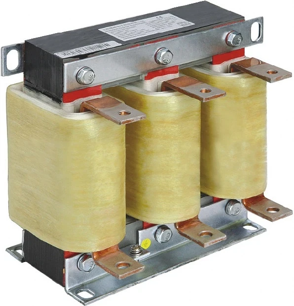
Record each phase or winding using the manufacturer's designated terminal identification. On a shared magnetic structure, connection details and the treatment of other windings may affect the comparison. Ask for the intended test configuration rather than assuming that three terminal pairs can be treated as three independent laboratory inductors.
A phase difference is a reason to investigate, not a complete failure diagnosis. Repeat the measurement after checking connections and instrument setup. Compare winding resistance and physical observations through the separately approved methods. Discoloration, loose supports or unusual operating noise should be recorded, but none identifies an exact internal defect without further evidence.
If the measurement remains outside the approved criterion, keep the branch unavailable pending the responsible engineering decision. Do not alter core gaps, remove turns or change taps to make a field reading resemble a target. Such changes can affect current duty, losses and the branch response in ways that a simple inductance reading cannot establish.
Evaluate the reactor and capacitor as a branch
A filter branch is defined by more than the reactor alone. Record the capacitor connection and measured or documented capacitance using the appropriate method. Check whether a capacitor unit or fuse has been replaced since the previous baseline. A reactor that matches its own specification may still be unsuitable for a branch whose capacitance has changed.
For an ideal series LC branch, the natural frequency is f = 1 / (2π√(LC)), with f in hertz, L in henries and C in farads. This relation describes an idealized circuit, not the entire network. For an illustrative L of 0.001 H and C of 0.001 F, the calculated frequency is about 159 Hz. Those values are an example, not CHYN product ratings or a recommended tuning point.
The example assumes the L and C values refer to the same equivalent branch. It excludes losses, mutual coupling, network impedance and nonlinear behavior. Do not insert a line-to-line capacitor value into a phase model without checking the connection. A return-to-service decision may require a network study; see passive harmonic filter resonance for the broader interaction question.
Translate findings into a repair or purchase request
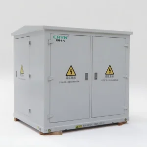
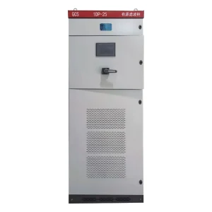
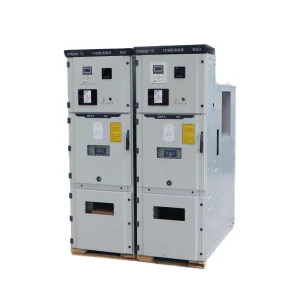
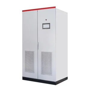
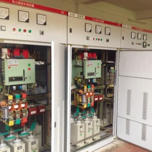
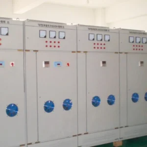
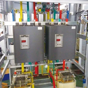
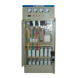
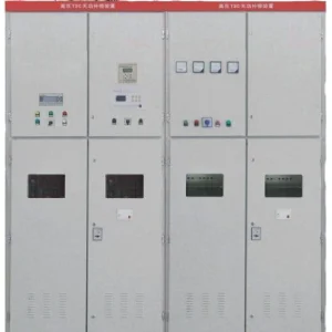
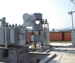
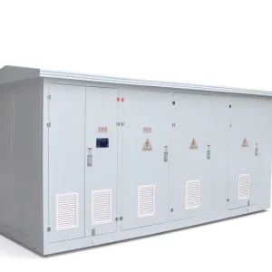
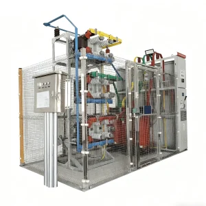
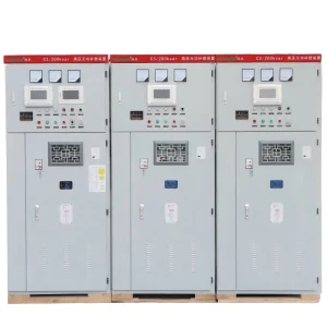
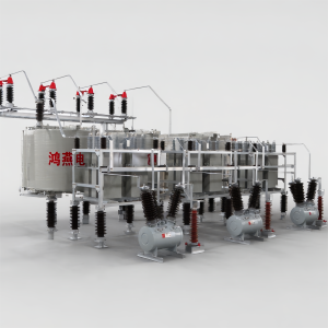
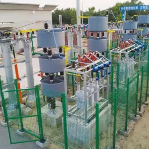
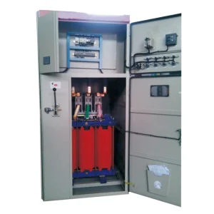
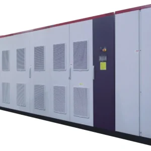
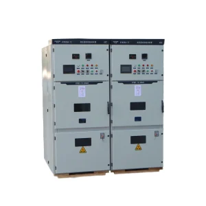
For a CHYN filter reactor inquiry, provide the branch drawing, capacitor details, reference report, measured results and all test conditions. Include the operating frequency, current duty and environment from the project specification. A photograph helps identify the construction but cannot establish inductance, insulation suitability or thermal capability.
If replacement is proposed, compare the full component requirements rather than matching a single millihenry value. Review mounting, connections, thermal protection and the approved branch design. The separate filter reactor replacement checklist covers this procurement and installation decision. Keep the measurement record as an input to that decision rather than treating it as the whole replacement specification.
After authorized work, restore connections against the approved drawing and complete the required inspection and functional checks. Establish a new baseline under documented operating conditions. If the test method changed, preserve the old results and explain why the new baseline is different. That explanation is more useful at the next maintenance visit than a spreadsheet containing unexplained numbers.
Educational background: passive filter behavior
This IIT Delhi lecture explains passive power filters. It helps connect the reactor measurement with the behavior of the complete branch. It does not demonstrate safe isolation or define a field acceptance procedure for any specific installed cabinet.

Watch the educational lecture on YouTube.
Frequently asked questions
Can a continuity test confirm inductance?
No. Continuity indicates an electrical path under the instrument's test conditions. It does not establish the winding inductance, rated-current behavior, losses or suitability for the capacitor branch. Choose the test method according to the actual maintenance question.
Can a handheld LCR meter replace a factory report?
Not automatically. Its frequency and excitation may differ from the specified test conditions. Use it only within an agreed method, record its setup and compare against a reference that the manufacturer or responsible engineer considers appropriate.
Is any phase difference a failed reactor?
No universal conclusion follows from phase difference alone. First check terminal identification, connection conditions and repeatability. Apply the documented acceptance criterion and investigate persistent differences with the manufacturer before returning the branch to service.
Why record capacitance during a reactor investigation?
The reactor operates as part of a branch whose behavior depends on both inductance and capacitance. Changed capacitor units, fuses or connections can alter the branch even when the reactor itself meets its specification. Preserve both component records.