
 Zhejiang Hongyan Electric Co., Ltd.

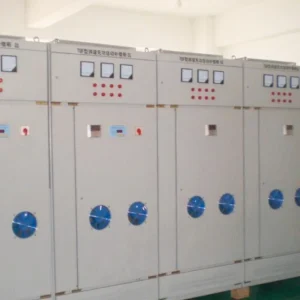
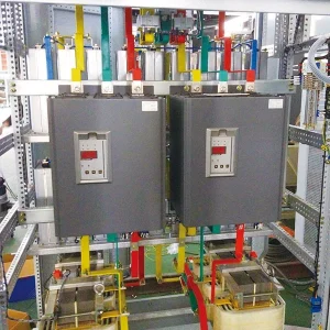
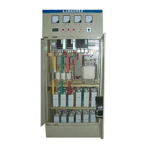
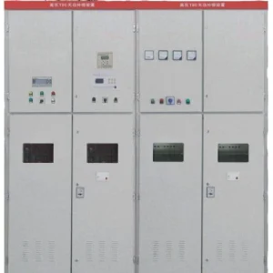


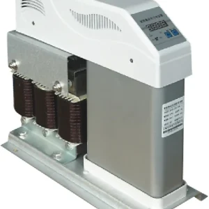
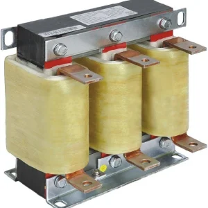
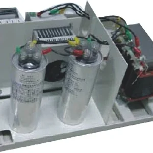
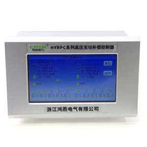
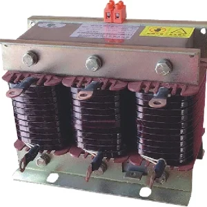
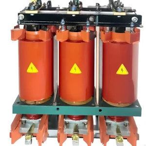
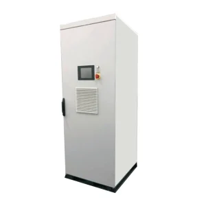
Capacitor bank unbalance protection testing should prove the measurement, relay logic, alarm, trip circuit and return-to-service condition for the actual bank connection. A relay pickup test alone cannot establish that the installed protection will isolate the correct bank. Start with approved drawings and settings, define safe test boundaries, then document what each test proves and what remains untested. This guide is a planning checklist for qualified commissioning teams working on medium- and high-voltage capacitor banks. It does not provide live switching instructions, universal relay settings or permission to create a capacitor failure on an energized installation.
Identify the bank arrangement before choosing test quantities
Collect the current single-line diagram, bank connection drawing, capacitor-unit schedule, fuse arrangement and protection schematic. Identify single-star or double-star construction, grounding, series sections and parallel groups. Locate every CT and VT used by the protection. Different arrangements produce different quantities for detecting internal unbalance, and the selected relay function must match the measurement scheme. An input labeled unbalance is insufficient evidence without the drawing that explains what it measures.
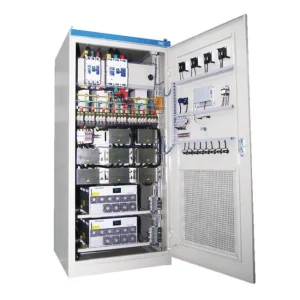
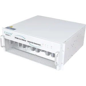
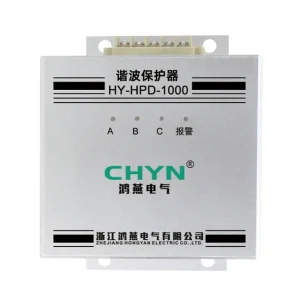
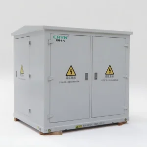
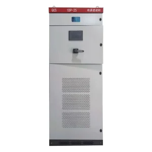
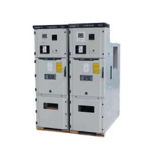
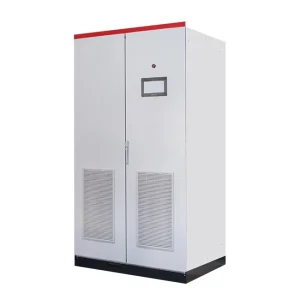
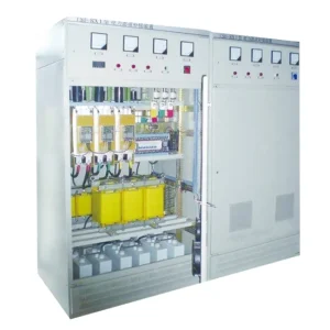
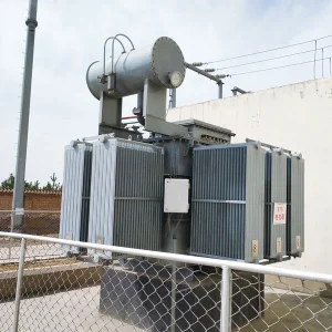
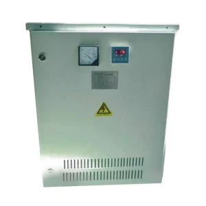
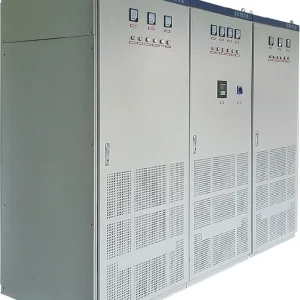
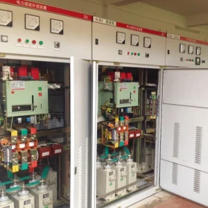
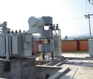
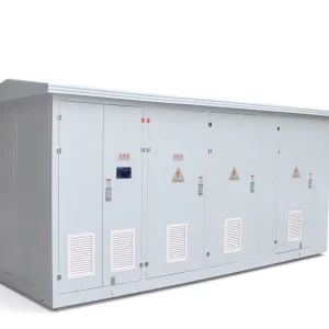
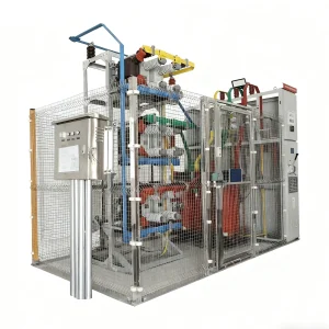
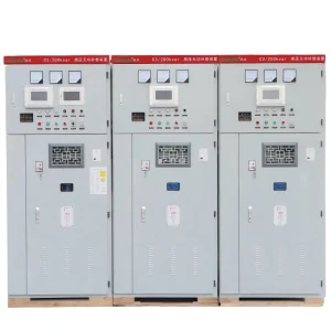
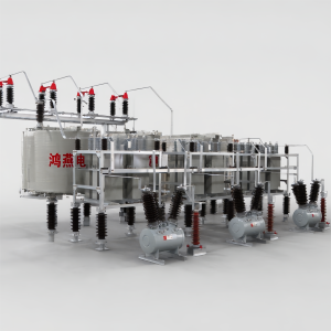
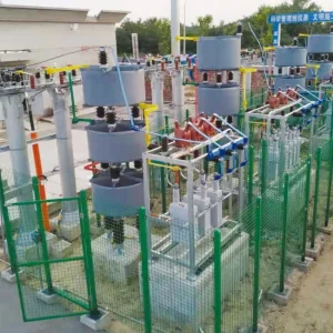
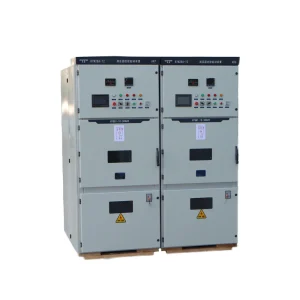
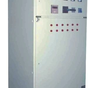
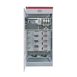
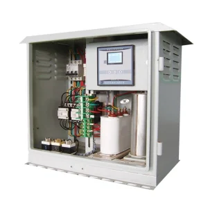
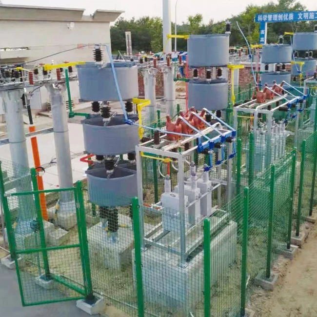
Check that installed components correspond to the records. Unit replacement, a changed fuse arrangement or an altered neutral connection can affect the protection assessment. Resolve discrepancies before testing settings derived from the old arrangement. The CHYN HYTBB outdoor-frame capacitor bank is relevant to projects with configurable bank and protection arrangements. Its photograph identifies the product family; it cannot confirm a particular installed connection, relay option or alarm threshold.
Separate the study from the commissioning procedure
The protection study should explain the internal failure conditions to detect, the associated stress on remaining components and the intended alarm or trip response. The commissioning procedure translates the approved settings and logic into controlled checks. A test technician should not be asked to invent pickup values from a generic table. Confirm the approved settings revision, relay model, firmware, instrument ratios and function configuration before connecting test equipment.
Ask which external conditions can influence the measured quantity and how the installed scheme treats standing unbalance. Record any compensation, restraint or blocking features that are actually provided. Do not assume that a function described for one relay exists in another model. The broader capacitor bank unbalance-protection guide addresses scheme selection; this article concentrates on the evidence needed to verify the chosen installation.
Plan isolation and define exactly what the test reaches
Capacitors can retain stored energy, and isolation of an incoming feeder does not by itself establish a safe work condition. Apply the site's approved switching, isolation, verification, discharge and grounding procedure through authorized personnel. Address auxiliary power, instrument circuits, remote control and possible backfeeds. Test equipment and connections must be suitable for the circuit. This planning guide cannot determine safe access or discharge time for an individual bank.
Mark the limits of every test on a schematic. Secondary injection can verify the relay input response and selected logic, but its proof of upstream CT wiring depends on where the signal is injected. A test at the relay terminals bypasses more of the installed circuit than a test made through approved test facilities farther upstream. Describe that distinction in the report. Where primary measurement-chain checks are required, use the engineer-approved method and document the additional coverage.
Build a staged evidence matrix
The following matrix is a suggested commissioning framework. It contains qualitative acceptance questions rather than invented universal pickup or timing values. Populate numerical criteria from the approved settings and relay instructions. Record the test connection, injected quantity, expected response, observed response and evidence file for each case.
| Test stage | Evidence to retain | What it can establish |
|---|---|---|
| Drawing and settings review | Bank arrangement, ratios, configuration and approved revision | The intended scheme matches the supplied design |
| Measurement-chain verification | Input association, polarity, scaling and test boundaries | The relay receives the intended measured quantity |
| Pickup and timing | Injected values, settings and recorded operation times | Enabled functions respond within approved criteria |
| Output and trip-path checks | Contacts, interlocks, breaker status and event records | The selected logic reaches the required equipment |
| In-service baseline | Stable bank condition, measured unbalance and compensation state | A documented reference exists for future comparison |
Maintain a separate result for each stage. Passing the relay's internal logic does not justify marking an untested breaker trip circuit as passed. If a plant outage restriction prevents a complete functional check, state the restriction and the remaining test explicitly. Assign responsibility and an approved completion opportunity before treating the protection system as fully commissioned.
Verify alarm and trip functions independently
Prepare cases below and above each relevant threshold using the approved procedure. Record pickup, dropout where applicable, timer behavior and reset requirements. Check the correct input scaling and units before interpreting the result. If a scheme uses both magnitude and phase information, or a restraint quantity, include the combinations required by its actual logic. Testing only one current magnitude may leave an important condition unexplored.
Verify that alarm and trip have their intended separate destinations. An alarm should reach the specified local and remote indications; a trip should operate the required circuit with the approved interlocks and lockout behavior. Include the relevant enable, block and maintenance states. Do not test a blocking condition by defeating live protection without an authorized procedure. Save relay event reports as well as the test-set result so that the recorded operating sequence can be reconciled.
A published Austin Energy commissioning document includes capacitor-bank trip checks, control indications and in-service measurements. It is a useful example of testing beyond a relay display. Its equipment-specific commands and utility procedures are not instructions for another installation. Develop the site checklist from the approved project drawings and protection requirements rather than copying its switching sequence.
Do not confuse a low unbalance reading with proof of a healthy bank
A University of Idaho thesis on capacitor-bank unbalance protection discusses how failures in different sections can partially or fully cancel in the measured unbalance. The practical boundary is important: a small residual alone cannot establish that every capacitor element is healthy. The thesis investigates enhanced detection; it does not show that every commercial relay implements the proposed method.
Keep commissioning evidence from unit checks, bank inspection and protection testing together. If a changed reading appears after maintenance, compare the unit schedule, connection records and raw measured quantities before attributing it to harmless tolerance. Preserve phase information where the installed scheme supplies it. Ask the protection engineer which additional checks are necessary when cancellation or reduced sensitivity is relevant to the bank construction. Do not claim complete internal-fault coverage from one successful injection.
Capture a trustworthy baseline after restoration
Before energization, confirm that temporary test connections and test modes have been removed through the approved restoration checklist. Verify the final settings revision, enabled functions, output links, alarm destinations and remote-control status. Record who checked the restoration and which operational authority released the equipment. An accurate relay test can still leave an unsafe installation if a temporary block remains active or an output circuit is left disconnected.
When an authorized in-service check is performed, record operating voltage, bank configuration, load state, measured unbalance and relevant environmental or thermal conditions. Use the relay manufacturer's method for any standing-unbalance compensation, and only after the bank condition has been verified. Keep raw readings before and after compensation. A reference adjustment should not hide an unexplained change. Obtain approval for the baseline rather than accepting a convenient near-zero display.
Coordinate this record with the medium-voltage capacitor-bank protection coordination review and the capacitor-bank reclosing-delay assessment. These cover different parts of the operating sequence. A successful unbalance trip does not prove that reclosing is appropriately restrained or that every external fault is selectively cleared. Identify the interfaces and include the applicable functional checks in the overall commissioning scope.
Prepare maintenance triggers and a useful handover package
Retain the as-built drawings, capacitor-unit arrangement, protection study, settings file, relay configuration, test-set files, event reports and signed restoration checklist. Index these records by bank identifier and revision. Include the approved baseline and the limitations of the performed tests. A concise summary should tell the operating team which alarm requires investigation, which condition prevents energization and who can approve a change. Avoid undocumented local conventions that disappear when staff change.
Define when the baseline and functional checks must be reconsidered. Relevant triggers include capacitor replacement, a changed bank connection, CT or VT work, relay replacement, settings changes and unexplained trips. The necessary retest scope depends on the change; it should be assigned through the site's maintenance and protection process. Preserve the earlier record for comparison rather than overwriting it with a new compensated reading. This makes developing problems easier to distinguish from a deliberate design revision.
For a new enquiry, provide CHYN with the system voltage, bank capacity, proposed connection, unit arrangement, grounding information, fault-study inputs and required protection interfaces. Ask which components and tests are included in the supplied package and which remain with the site commissioning team. Agree witness points, acceptance documents and responsibility for final settings. Clear interfaces reduce the chance that factory checks and site checks each assume the other party proved the complete trip path.
Educational background: why capacitor banks supply reactive power
The NPTEL IIT Guwahati lecture below explains reactive compensation and capacitor placement. It provides context for the bank's role in the network; it is not a relay-testing demonstration. Use the approved relay manual and site procedure for the actual protection test.

Watch the educational lecture on YouTube.
Frequently asked questions
Does secondary injection prove the complete protection system?
It proves the functions reached by its connection and test scope. CT circuits, upstream wiring, output links and breaker operation may require additional approved checks. State each tested boundary explicitly.
Can generic alarm and trip settings be used?
No. Settings depend on bank construction, expected failure conditions, instrument quantities and relay logic. Use an approved protection study and verify the exact settings revision installed in the relay.
Does zero measured unbalance prove all capacitors are healthy?
No. Some failure patterns can cancel in the measured quantity. Combine the protection record with the approved bank inspection and unit-verification process, and assess the limitations of the selected scheme.
When should the standing-unbalance reference be updated?
Only through the approved procedure after the bank condition and operating state have been verified. Preserve raw before-and-after readings and investigate unexplained changes before recording a new reference.