
 Zhejiang Hongyan Electric Co., Ltd.





































Capacitor banks supply leading reactive power near motors and transformers so the grid carries less lagging kvar—that is what do capacitor banks do in everyday plant language. The same shunt capacitor bank action raises power factor, lowers line current, trims I²R losses, supports bus voltage, and frees usable transformer capacity. This article walks that function chain, marks the harmonics and overcorrection boundaries, and shows how a medium-voltage package like HYTBB embodies those jobs.
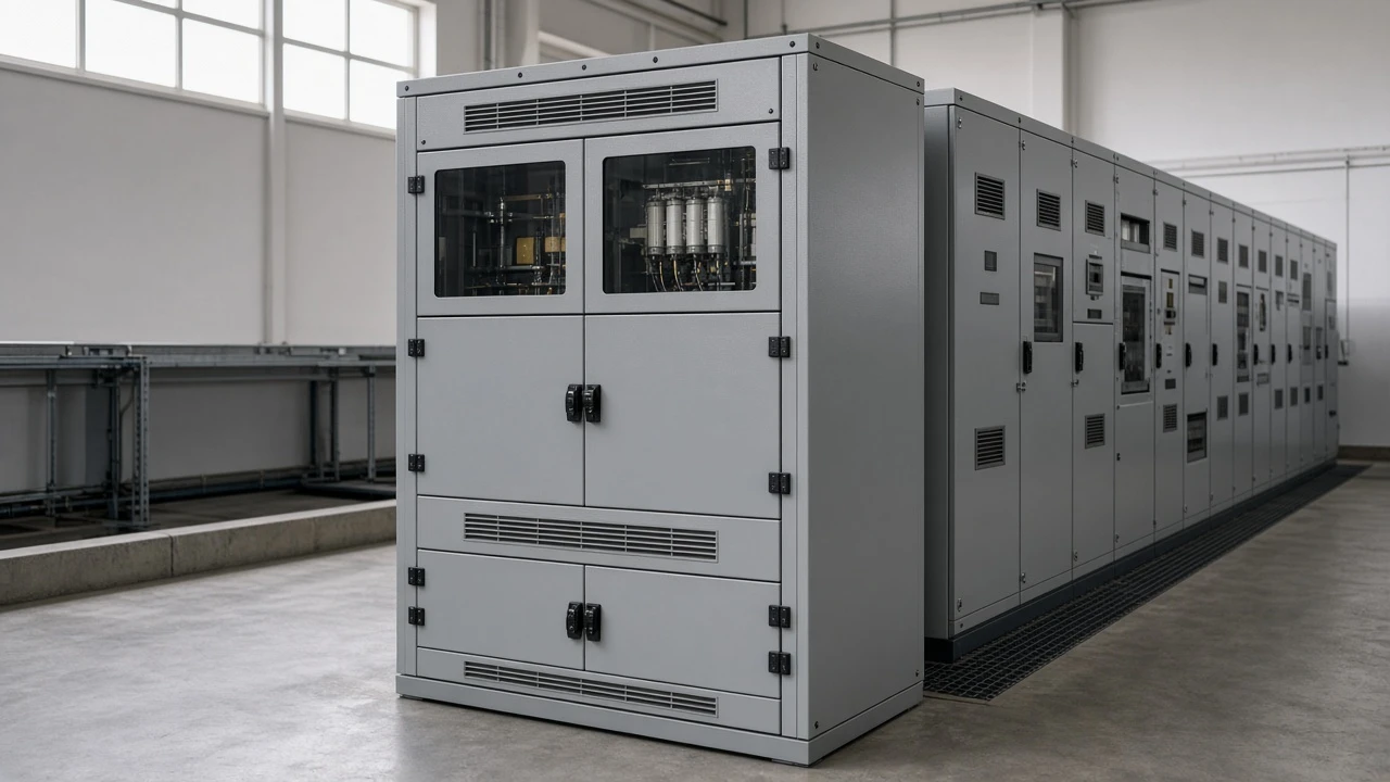
The core jobs: supplying leading kvar where motors need it
Capacitor banks supply leading kvar locally so inductive load magnetizing current does not have to travel the whole feeder from the utility source.
An inductive load—motors, transformers, many furnaces—draws lagging reactive power. That reactive power does little useful mechanical work, yet every upstream cable and transformer still carries it.
A shunt bank connected across the bus draws leading current. The two reactive components partly cancel at the connection point, which is the physical job behind reactive power compensation.
| Job | Physical action | What the plant notices |
|---|---|---|
| Supply leading kvar | Capacitive current offsets lagging magnetizing current | Less reactive demand measured upstream |
| Improve power factor | Net Q falls while P stays about the same | Higher PF on meters and bills |
| Cut current and losses | Lower apparent power → lower amps → lower I²R | Cooler feeders; less wasted heat |
| Support voltage | Less Q·X drop on reactance-heavy lines | Firmer bus or end-of-feeder voltage |
| Free capacity | Same kW needs fewer kVA | Headroom on transformers and cables |
That table is the answer map. Later sections unpack each row without turning this page into a sizing worksheet—that work already lives in CHYN’s capacitor bank for power factor correction guide.
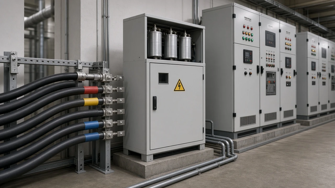
How capacitor banks improve power factor
They shrink the reactive side of the power triangle so power factor—real power divided by apparent power—moves closer to the project target.
For sinusoidal conditions, power factor is P/S, with S = √(P² + Q²). When the bank injects capacitive kvar, net Q at the metering point falls. P for the process can stay the same, so S shortens and power factor correction appears on the meter.
Utilities care because reactive demand still occupies network assets. Plants care because tariffs, demand charges, or contractual PF limits often punish a chronically lagging site.
Community electricians on field forums also note that penalty severity varies widely by utility, so “will it pay back?” is a local arithmetic problem, not a universal promise.
A practical target is usually a solid lagging band near 0.95 rather than chasing 1.0. Fixed banks on swinging loads can overshoot into leading territory; automatic switching steps kvar with the load when variability is high.
Cutting line current and I²R losses
Higher power factor lowers line current for the same kilowatt load, and copper losses fall roughly with the square of that current.
Three-phase current tracks apparent power: I = P / (√3 × V × PF). Raise PF and I drops even if the process still draws the same P.
Because feeder and transformer winding losses scale with I²R, a modest amp reduction becomes a larger loss reduction.
Independent technical teaching materials walk a clear illustration: a 500 kW load at 480 V correcting from 0.75 to 0.95 lagging needs on the order of 277 kvar, cuts line current by about 21%, and cuts I²R losses by nearly 38% on the path that previously carried the reactive share. Treat those figures as a worked classroom example, not a CHYN factory test result.
| Quantity | Before (PF 0.75) | After (PF 0.95) |
|---|---|---|
| Real load | 500 kW | 500 kW |
| Apparent power | ≈667 kVA | ≈526 kVA |
| Line current (480 V) | ≈802 A | ≈633 A |
| Relative I²R on that path | 100% | ≈62% |
Energy “savings” language should stay honest: the bank does not replace process kWh the way a drive retrofit might. It removes unnecessary reactive amp-turns from the path so less real power is wasted as heat upstream of the load.
Voltage support—and why overcorrection raises voltage
Reducing reactive flow through line reactance lifts and flattens voltage; pushing too many leading amps can raise voltage above the band you wanted.
Approximate feeder drop behaves like ΔV ≈ (P·R + Q·X) / V. On many distribution and industrial feeders, X dominates R, so the Q·X term matters. Local kvar support therefore doubles as voltage support when the bus was sagging under lagging load.
The same physics runs in reverse. Leading current through reactance produces a voltage rise.
Field discussions among utility and plant electricians repeatedly flag light-load overcompensation: night shifts or idle feeders with fixed banks still online.
IEEE educational summaries also note that added kvar relative to short-circuit level raises bus voltage on the order of Q/S per unit—useful intuition when someone proposes a very large fixed bank on a weak bus.
Important: A capacitor bank that is “always on” can leave you with a leading power factor and a high-voltage complaint when production drops. If load swings, prefer automatic switching aimed at a lagging band near 0.95, and check light-load voltage—not only the peak-load PF number.
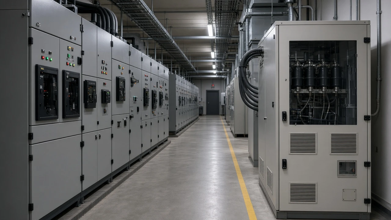
Releasing transformer and feeder capacity
Lower apparent power for the same real load frees transformer capacity and feeder ampacity that reactive current was consuming.
Cables, breakers, and transformers are limited by current and kVA, not by “how hard the motors are working” in kilowatts alone. When PF is poor, you can hit thermal limits while the process still has unused real-power headroom.
Shunt compensation that removes upstream reactive flow releases that headroom—often described as increasing the effective capacity of electrical equipment.
Bonneville Power Administration’s industrial power-factor guidebook framed the same idea for utilities and plants decades ago: shunt capacitors raise PF, reduce losses and voltage drop, and release system capacity. That remains the procurement-relevant job when a transformer upgrade is the expensive alternative.
Capacity release is local to everything upstream of the bank. A bank at the main bus helps the service transformer; a bank at a motor MCC helps that feeder first. Placement is part of the function, not a footnote.
What capacitor banks do not do alone
They correct fundamental-frequency reactive power; they do not erase harmonic distortion by themselves, and energizing them has switching side effects.
Nonlinear loads—VFDs, rectifiers, some furnaces—create distortion that can make a “bad PF” story incomplete.
Forum engineers warn that if the problem is mostly distortion power factor, capacitors alone may be the wrong tool.
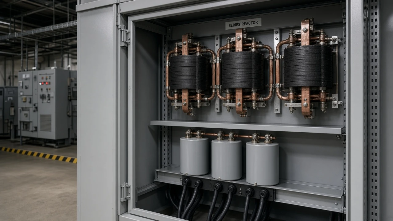
A bank’s capacitance also forms a resonant circuit with network inductance; if that resonance sits near a harmonic the plant injects, currents amplify and capacitors overheat. Series reactor (detuned) designs and separate harmonic filters exist for that boundary.
Switching a bank is another job boundary. Energization can create inrush and transient overvoltage, especially in back-to-back cases.
For controlled closing and inrush limiting, use CHYN’s dedicated guide on point on wave switching for capacitor banks rather than expecting this function article to double as a switching design manual.
Related reading when you move from “what they do” to “how to buy or switch”:
- Capacitor bank for power factor correction — sizing, fixed vs automatic, harmonics buyer path
- Point on wave switching for capacitor banks — inrush and controlled closing
- Parent hub: High Voltage Power Factor Compensation Series
HYTBB product recommendation for medium- and high-voltage shunt banks
HYTBB packages the shunt-bank jobs above for power-frequency systems in the medium- and high-voltage range used on industrial and substation buses.
On the live product page, the HYTBB medium and high voltage reactive power compensation cabinet is described as a shunt capacitor bank that compensates inductive reactive power. It states the familiar outcomes: improve power factor, enhance voltage stability, reduce energy losses, and increase effective capacity of electrical equipment.
Published scope on that page includes power-frequency service from about 1 kV to 35 kV, with a parameter table listing rated voltage 10(6)–35 kV, 50 Hz, and capacity from 50 to 20,000 kvar. The cabinet can run fixed or with manual or automatic switching of groups.
Series reactor branches are described for limiting inrush and helping with harmonic conditions—typical percentages cited on the page are about 4.5–6% on 6 kV systems and 12–13% on 10 kV systems.
Product feature text also cites improving system power factor up to 0.95 or higher and reducing line current by 10–20% under the conditions the page addresses. Read those as manufacturer performance statements for the HYTBB family, not as a substitute for your site’s measured load study.
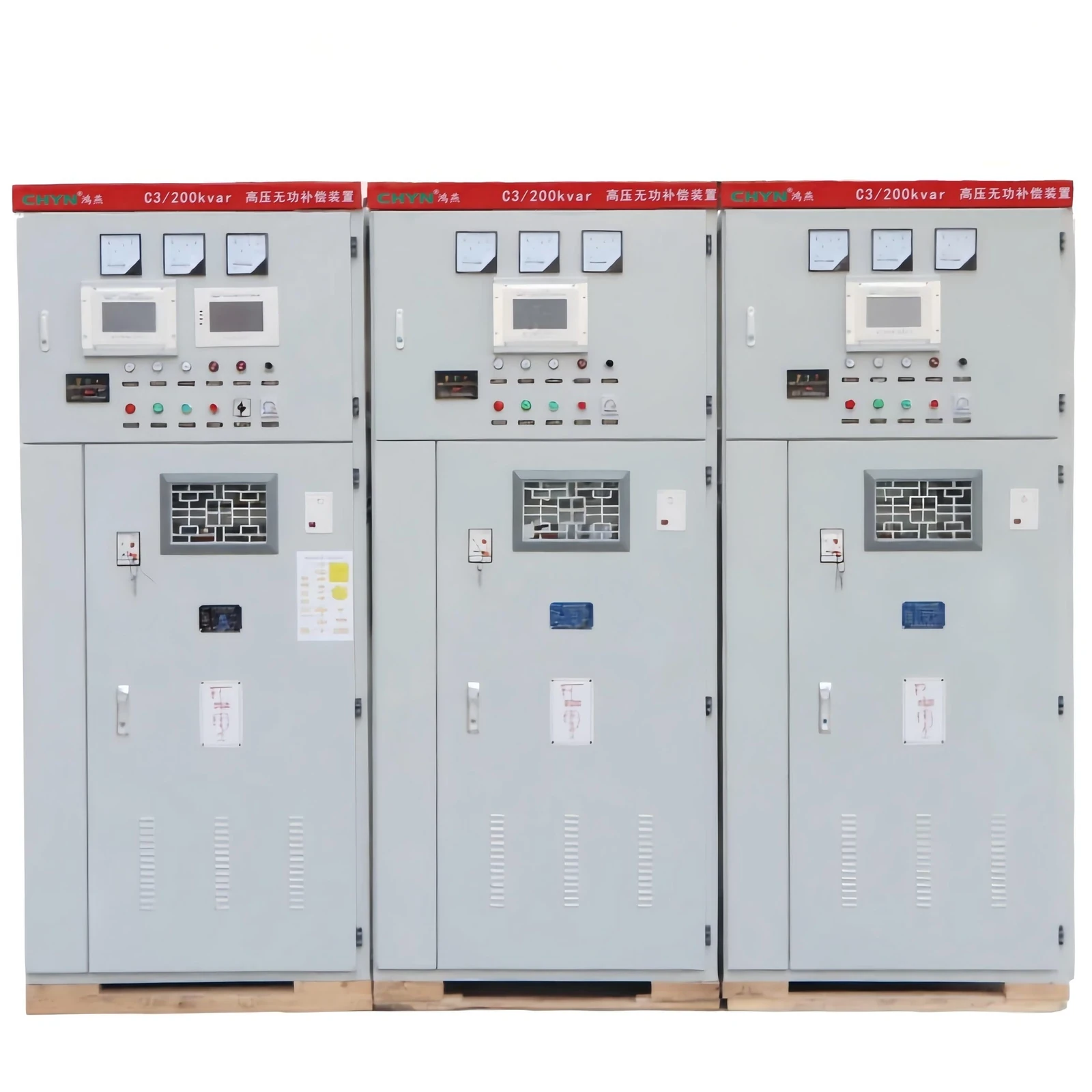
Choose HYTBB when you need an MV/HV shunt compensation cabinet aligned with those jobs. Look elsewhere first when the dominant problem is fast unbalanced distortion better served by SVG/AHF topologies, or when you only need a low-voltage end-point box. Browse sibling frames and outdoor types on the high voltage power factor compensation series hub before you freeze a bill of materials.
FAQ
What do capacitor banks do in simple terms?
They supply leading reactive power next to lagging inductive equipment so upstream circuits carry less reactive current. That single action is what unlocks better power factor, lower amps, less I²R heat, firmer voltage, and freed kVA.
How do capacitor banks improve power factor?
By cutting net kvar at the metering point while real power stays roughly constant, they shorten apparent power and raise P/S. That is classic power factor correction with shunt capacitors.
Do capacitor banks reduce electricity losses?
They reduce the extra line current caused by poor PF, so I²R losses on upstream paths fall. They do not magically remove the process kilowatt-hours your machines still need.
How do capacitor banks help voltage?
Less reactive flow through line reactance means less Q·X voltage drop, which is voltage support. Oversized or always-on banks can create a leading condition and raise voltage at light load.
Can a capacitor bank free transformer capacity?
Yes. Lower kVA for the same kW frees transformer capacity and feeder ampacity that reactive current was consuming upstream of the bank.
What if the bank is too large (leading power factor)?
Leading PF can raise voltage, increase current again, and annoy both protection and the utility. Prefer a lagging target near 0.95 and use automatic switching when loads swing.
Do capacitor banks fix harmonics by themselves?
No. They address fundamental reactive power. Distortion and resonance need measurement, often a series reactor or a dedicated filter strategy.
Where does an MV package like HYTBB fit?
HYTBB is a CHYN medium- and high-voltage shunt compensation cabinet for roughly 1–35 kV power-frequency systems that need the PF, voltage, loss, and capacity jobs in one engineered lineup.
References
- IEEE Technology Navigator — Capacitor Banks
- GIEE — Capacitor Banks in Power Systems: How Reactive Compensation Cuts Current, Losses, and Voltage Drop
- DOE / BPA Industrial Power Factor Analysis Guide Book via OSTI — Industrial Power Factor Analysis Guide Book
- Mike Holt’s Forum — Capacitor Banks
- Mike Holt’s Forum — Capacitor Bank Placement