
 Zhejiang Hongyan Electric Co., Ltd.





































Closing a capacitor step onto a busbar that already carries an energized step fills the new step from its neighbour instead of from the supply transformer, and that is what makes back to back capacitor bank switching a harder duty than energizing the first bank of the day. The current arrives through a few metres of copper rather than through the impedance of the network above it, so it peaks higher and swings faster.
What follows starts with the recognition test you can run on your own drawing, then works through the loop that causes it, what the current threatens, the quantities from one measured utility case, and the mitigation choice. For the equipment itself, the definition sits in what capacitor banks are.
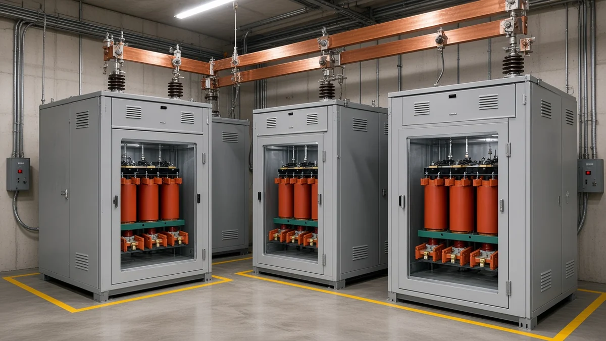
How to Tell From Your Single Line Diagram That You Have a Back-to-Back Duty
If your single line diagram and nameplate show two or more capacitor branches on the same bus section, and any of those steps can be closed while the others stay energized, treat the installation as a back-to-back duty and ask for the inrush figure before the next step is ordered. The five checks below decide whether you need to commission that study; they cannot stand in for it.
- Two or more capacitor branches on one bus section. Count the capacitor symbols hanging off the same stretch of busbar, and count across a tie breaker too, because banks on opposite sides of a closed tie are still neighbours.
- Steps that can close while the others are live. Look for one switching device per branch; if the whole bank closes through a single device, no step can be energized while its neighbours are live.
- The kvar per step and the system voltage, from the nameplate. That pair fixes the capacitance of each branch, and the branch you are closing is filled by the branch already in service.
- The length and route of the connection between steps. Pace it out on the drawing or in the room, because that copper is the loop inductance, and a short, tidy run is electrically the harsher case here.
- Whether a series reactor is already fitted in each branch. A bank that arrived with a reactor per step has answered the question in hardware, and the reason behind that choice is worth knowing before you change anything.
Equipment paperwork often settles check 2 on its own. The HYTBB medium- and high-voltage compensation cabinet page states that its compensation can be fixed or configured for manual or automatic group switching, so a cabinet ordered that way is a multi-step installation by construction.
A nameplate may print it as group switching, or as step / stage switching, and any of those words means the blocks are added and dropped one at a time under a controller.
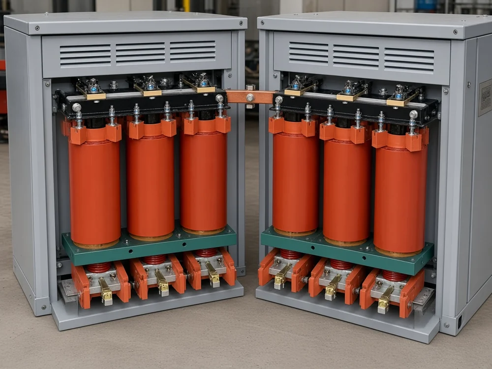
Substation crews describe the same layout from the other end. Two switches per bus section, one per capacitor step, with a series inrush reactor behind each switching device, is how they report their own installations — an arrangement that only makes sense if the second close is the hard one.
Residual charge and discharge time govern the reverse operation, because a step that has just dropped out still holds voltage. The HYTBB cabinet page publishes a discharge circuit that brings residual voltage below 50 V within three minutes of disconnection, which is a design figure for that cabinet rather than a number to assume for every bank on your site.
The reason each step hangs across the bus as its own parallel branch is taken apart in how capacitor banks are connected.
Why the Second Step Draws Its Current From the First, Not From the Transformer
The energized bank beside the one you are closing behaves as a charged source a few metres away, so the discharge loop between banks is set by the inductance of that short connection rather than by the inductance of the system above it. Both the peak and the oscillation frequency climb as a result, and for the first few milliseconds the supply barely takes part.
Through those milliseconds the local capacitor circuits dominate what reaches the bus, and the source voltage and source inductance drop out of the equivalent circuit. Capacitor bank inrush current becomes a layout question at that point, since the only impedance left in the way is the busbar, the cable and the stray inductance between the two branches.
Isolated bank switching is the mild version of the same event, and it is the version most engineers have already watched. Energizing one bank against the source alone typically lifts the voltage to between 1.2 and 1.8 per unit and rings at 300 to 1000 Hz.
Watch the frequency the loop rings at. A peak that looks survivable on a power-frequency rating is a different proposition when it arrives as a fast oscillation, because the ability of a switching device to make and hold that current has to be judged at the frequency the loop rings at, and not at the frequency its nameplate assumes.
That is what separates back-to-back capacitor bank switching from every other closing operation on the same bus, and it is why the step that gave nobody any trouble on commissioning day tells you nothing about the step you are adding next.
What the Inrush Threatens: Closing Contacts, Capacitor Fuses, Relays and CTs
The switching device takes the worst of it, because a prestrike across the closing gap drives a high-frequency current through contacts that have not yet touched. The same current then runs on through the fuses, the relays and the instrument transformers of that branch, none of which were chosen with this event in mind.
Prestrike and contact welding are the pair to watch at the device itself. In vacuum devices the contacts can weld together, in minimum-oil interrupters a prestrike has been reported to destroy the complete interrupter, and in SF6 devices it can damage the arcing chamber or the nozzle.
The current can reach the tens of kiloamperes, and the stress stays inside the local parallel capacitor circuit instead of travelling out into the rest of the network. That containment explains why a violent local event can leave the wider system looking untouched while the switchgear quietly pays for it.
Past the contacts the damage list is short and specific. The capacitor fuse I²t withstand in that branch is the second rating the event can pass, protective relays can operate on a current that is entirely legitimate, and the current transformers in the branch can be pushed to excessive secondary voltage.
The capacitor units on both sides of the loop carry that current as well, since they are the two ends of the same discharge path. A capacitor switching device is specified against precisely this moment: its close-and-latch capability, read at the transient frequency of the loop instead of at power frequency.
What the Numbers Looked Like on One Documented 23 kV Feeder
One utility measurement campaign put the whole arithmetic on paper at distribution voltage. On a 23 kV feeder carrying three radio-controlled 1800 kvar banks, the loop between the first and the third bank worked out to a calculated peak of 1019 A at a natural frequency close to 2000 Hz.
The recording agreed on the frequency and disagreed on the peak. The measured phase current topped out near 600 A, which the report puts down to current transformer saturation at the transient frequency, while the FFT of the filtered waveform placed the dominant frequency around 2000 Hz — the figure the calculation had already produced.
| Quantity in that case | Value | The condition it belongs to |
|---|---|---|
| Feeder and source | 23 kV feeder off a 46.7 MVA 115/23 kV transformer | one utility distribution feeder, recorded in service |
| Banks on the feeder | three radio-controlled 1800 kvar banks | spaced 2870 ft, 4200 ft and 3300 ft apart along the run |
| Connection inside the loop | 4200 ft of 3-336 aluminium tree wire at 0.494 Ω, giving 1.38 mH | the route between bank 1 and bank 3, which is the loop inductance for that pair |
| Capacitance | 293.9 Ω per bank, giving 90.3 µF, with 4.51 µF as the series equivalent | each 1800 kvar bank at 23 kV |
| Natural frequency, calculated | about 2036 to 2063 Hz | the loop from bank 1 to bank 3 |
| Surge impedance | 18.4 Ω | the same loop |
| Peak inrush, calculated | 1019 A | the same loop, arithmetic only |
| Peak, recorded | near 600 A | measured phase current, understated because the CT saturated at the transient frequency |
| Dominant frequency, measured | around 2000 Hz | FFT of the filtered recording, which matched the calculation |
| Isolated-bank ceiling, for contrast | 2 per unit maximum voltage transient | energizing a bank with no charged neighbour beside it |
Every figure in that column belongs to one feeder's conductor, spacing and voltage class. The saturated CT belongs in the record: the instrument understated a current the arithmetic had already found, which is worth remembering before a single recording is treated as the last word.
Read the table as proof that the calculation can be done and then checked against a recording; the values themselves stay with that feeder. Why feeders and substation busbars carry banks like these in the first place is covered in why substations use capacitor banks.
Choosing Between a Series Reactor, Pre-Insertion, a Capacitor-Duty Switch and Step Sequencing
Four answers are established and none of them is free: a current-limiting series reactor raises the loop inductance permanently, pre-insertion damps only the closing instant, a device built for capacitor duty survives the current instead of reducing it, and sequencing or splitting the bus removes the coincidence of two live steps without buying hardware. Which one fits depends on the loop, on how often the steps are switched, and on whether the bank exists yet.
| Option | What it changes in the circuit | What it costs the owner | When it is the one to specify |
|---|---|---|---|
| Current-limiting series reactor | adds fixed inductance to the capacitor branch, pulling down both the peak and the transient frequency | stays in circuit permanently, adding losses and reducing how much compensation the capacitors deliver | a new or retrofitted step where the connection between banks is short and the switching pattern is ordinary |
| Pre-insertion resistor / pre-insertion contact | inserts a resistor or an auxiliary contact for the first instants of closing, then bypasses it | extra mechanism inside the switching device, and no help whatsoever once the bypass closes | an existing bank where a permanent reactance would cost more compensation than the owner can spare |
| Capacitor-duty switching device | nothing in the circuit; the device is chosen to make and hold the current at the transient frequency | device cost, plus a rating argument that has to be won at the transient frequency instead of at power frequency | a new bank whose loop cannot be lengthened, where the duty is understood before the order goes out |
| Bus splitting and step sequencing | removes the coincidence, so no step closes while its neighbour is live on the same section | operating and control complexity, and a slower answer to changing reactive demand | a site with spare bus sections, or a controller that can be told which order to close in |
| Thyristor-switched capacitor (TSC) groups | closes at the voltage zero crossing, with no mechanical contact to prestrike | a different class of equipment, scoped to particular networks | fast repetitive switching, where a mechanical device would be worn out by the duty |
Important: a permanently placed fixed reactance costs something every hour it is in circuit — it increases energy losses in the system and reduces the effectiveness of the capacitors, so the reactance percentage is a compromise somebody has to sign off.
Reactors for this duty are small. Fixed inductors used against a back-to-back close are on the order of several hundred microhenries, while outrush-limiting inductors, which answer a fault close to the bank instead, are typically 0.5 to 2.0 mH. What a supplier quotes as an inrush current limiting reactor is the first of those two, and its value follows from the bank rating and the loop, which is why a catalogue default makes a poor starting point.
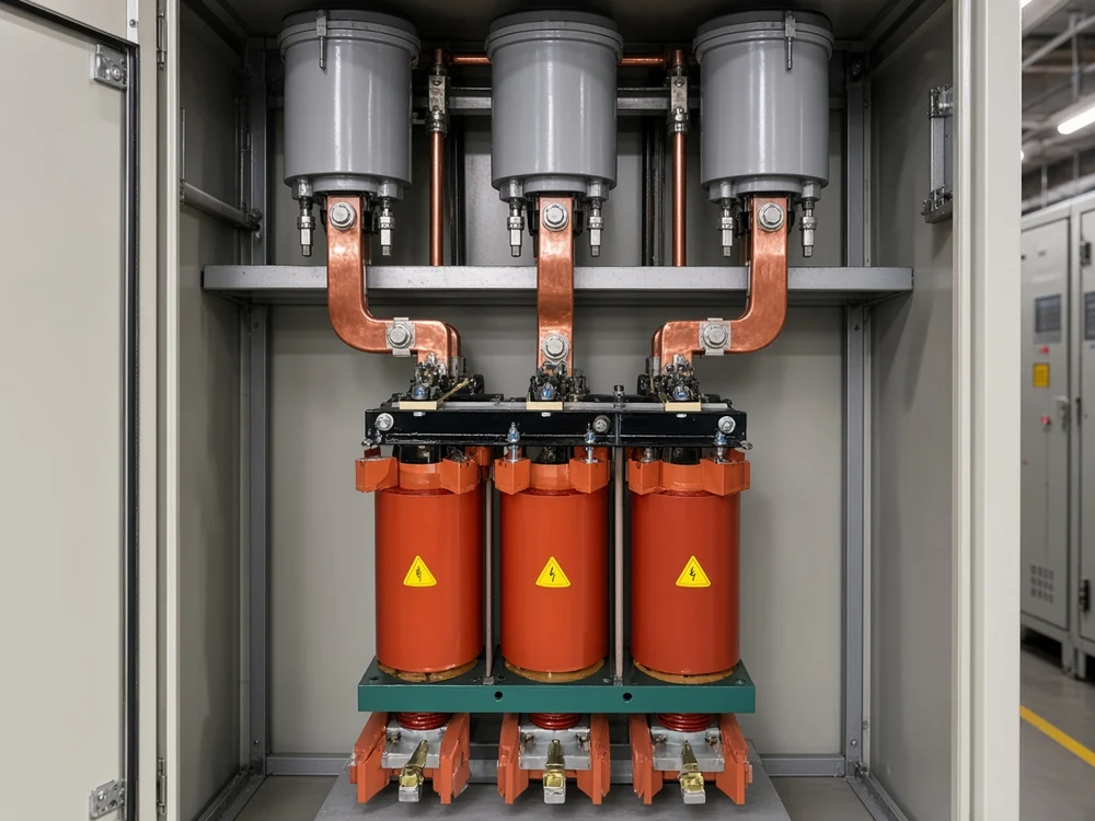
Controlling the instant of closing instead of the loop is the fifth route, and it belongs to point-on-wave switching for capacitor banks.
Where the duty comes from switching steps many times a day, solid-state switching changes the question altogether. The HYTSC dynamic compensation system page describes thyristor-switched capacitor groups that close at the voltage zero crossing, and states that this brings no inrush current and no operating shocks.
The product page puts that system on 6 kV and 10 kV networks, so it answers one slice of the problem rather than retiring the reactor question.
The split across the rest is mostly between banks that exist and banks that do not. Sequencing and pre-insertion act on an installation that is already built, while the reactor and the switching-device rating are decisions taken while the single line diagram is still open.
When an Inrush Calculation Stops Being Optional
Do the calculation as soon as a second step can be energized onto a live bus section through a short connection, because the figure only earns its keep once it has something to be measured against. A peak current on its own settles nothing.
Tip: ask for the peak and the transient frequency together — a current that sits comfortably inside a device's power-frequency rating can still exceed what the same device can make and hold at the frequency of the loop.
Two comparisons close the question:
- the momentary close-and-latch capability of the switching device, read at the transient frequency of the loop instead of at power frequency;
- the withstand of the capacitor fuses in the branch being closed, which carries the same current.
The trigger sits in the layout, not in a rating. Two or more branches on one bus section, independent closing, and a short run of copper between them together make the calculation part of the job, and a reader whose checks 1, 2 and 4 all came back positive already has the answer.
The cost of skipping it lands at commissioning, when a bank that every component test approves refuses to stay in service.
When the Bank Trips on Every Close but Every Test Passes
Engineers regularly describe a bank that trips the moment it is energized while the capacitors and the switch both test good, and the first move is the disturbance record rather than another component test. A nuisance trip on energization is a coordination problem before it is a hardware problem: overcurrent protection has to ride through a harmless inrush and still clear a genuine fault quickly, and those two jobs pull against each other.
From the field: engineers who post a capacitor bank that trips on every close get the same reply from their peers — show the disturbance recorder and the waveform before replacing anything, because the trip may have come from the transient state at startup.
- Pull the disturbance or fault record for the trip. The frequency in that waveform is the evidence: a fast oscillation well above power frequency points at the closing transient, while a power-frequency current points somewhere else entirely.
- Note which element operated. In one such report the peers reading it suspected a high-impedance line-to-line fault precisely because the phase time-overcurrent element operated while the instantaneous element stayed quiet, so the element that picked up is part of the evidence.
- Check the settings and the curve behind that element. A relay set for load protection on a branch that also has to survive an energization is a setting question, and it costs nothing to rule out.
- Test what feeds the bank, and not only the bank. A healthy capacitor and a healthy switch leave the cable, the connections and the upstream circuit unexamined.
None of that identifies a back-to-back transient on its own, and the field reports this pattern comes from are rarely resolved in public. What the record does is put a frequency and a waveform shape in front of you, and those are exactly what the close-and-latch comparison needs as its input.
How to Choose a Series Reactor That Fits Your Back-to-Back Duty
If the decision lands on a permanent series reactor, it is specified from the system voltage, the capacitor capacity and the reactance ratio, and the reactance you add stays in circuit for the life of the installation. The bank and its loop set the value; a catalogue only tells you what can be built.
The CKSC high-voltage iron-core series reactor page describes a reactor connected in series with capacitor banks to limit switching inrush current and control harmonic amplification in medium- and high-voltage compensation systems, supplied dry-type epoxy cast or oil-immersed, single- or three-phase. Its model code asks for the three quantities the recognition test already collected: the reactance percentage, the system rated voltage and the reactor capacity in kvar.
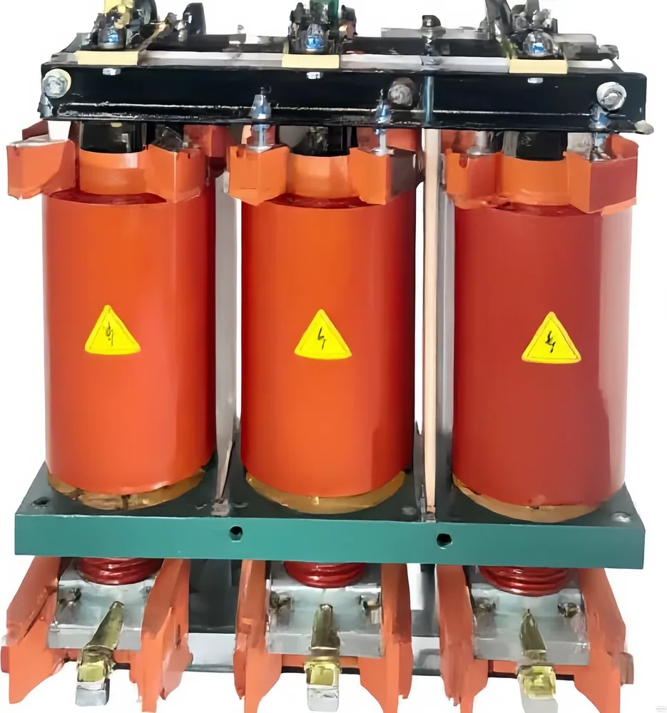
It is a different component from the low-voltage detuned tuning reactors sold for harmonic work, which move a branch's resonant point instead of limiting a closing current, and confusing the two is the easiest way to order the wrong reactor for this duty.
The trade-off travels with the recommendation. A permanently placed fixed reactance increases energy losses in the system and reduces the effectiveness of the capacitors, so the reactance ratio deserves a decision rather than a default.
A reactor is also the wrong answer where the duty comes from fast repetitive switching, where the constraint is the closing instant rather than the loop, and where a bank that already trips needs an engineering study before it needs a component.
Read the reactor page, then send the system rated voltage, the kvar per step and the number of steps, the reactance ratio if one has already been set, the distance between the steps, and the switching device already installed, so the reactor can be sized against the loop you actually have. Where the wider buying picture still needs framing, the application map for capacitor banks sets out which position a bank belongs in, and the high-voltage power factor compensation series holds the switched banks, thyristor-switched systems and voltage-regulation equipment that sit either side of a reactor decision.
FAQ
What is back-to-back capacitor bank switching?
Energizing a shunt capacitor bank while an adjacent bank on the same bus is already in service. Engineers also write it as back to back switching of capacitor banks, or as bank-to-bank switching, and the phrase points at how the installation is arranged, not at a class of equipment.
Why is the inrush worse than switching a single bank?
Because the charged bank next door supplies the current through a short, low-inductance loop, so the transformer and the network above the bus stop limiting anything for the first few milliseconds. Closing one bank on its own is held back by the source inductance and the bank's own capacitance, which is a far gentler event at a far lower frequency.
How high can the inrush current get?
It belongs to an order of magnitude rather than a fixed multiple. The transient can reach the tens of kiloamperes and it stresses the components of the local parallel capacitor circuit and not the network beyond them, and since published multiples of rated current contradict each other, the figure worth having is the one calculated for your own loop.
How do I tell whether my installation has this duty?
Read your own single line diagram and nameplate. Two or more capacitor branches on one bus section, steps that can close while their neighbours are live, and a short connection between those steps together mean the duty applies, and the kvar per step plus the system voltage are the first numbers any study will ask you for.
When is an inrush calculation actually necessary?
As soon as a second step can be closed onto a live bus section through a short connection. The result earns its keep by being compared against the close-and-latch capability of the switching device at the transient frequency and against the withstand of the fuses in that branch, so a figure delivered without those two comparisons has told you nothing.
My bank trips every time it is energized but all tests pass — what now?
Start with the disturbance record before ordering another component test. The waveform shows whether the current was a fast closing transient or something at power frequency, the element that operated narrows the search, and the settings and curve behind that element are worth ruling out before any hardware is replaced.
References
- General reference: utility capacitor switching — how the impedance of the discharge circuit between two banks is set by the inductance between them, what the current can exceed in a switching device and in capacitor fuses, and the established set of mitigations.
- Capacitor switching techniques — the local capacitor circuits that dominate the first milliseconds, the order of magnitude of the transient, prestrike damage in vacuum, oil and SF6 devices, and the loss penalty of a permanently placed reactance.
- Distribution Power Quality monthly event report — the measured utility feeder case behind the worked quantities, including the calculated peak, the recorded peak and the current transformer saturation that separated them.
- Inrush current — the general definition, why a discharged capacitor looks like a short circuit to the source, and why overcurrent protection has to tolerate inrush while still clearing genuine faults.
- What do ya'll use for cap bank switching — substation crews describing the device chains they run on switched banks and the series inrush reactors fitted behind each switching device.
- Capacitor bank tripping when it is energized — an engineer whose bank trips on every close with good component tests, and the peers pushing for the disturbance record before any replacement.