
 Zhejiang Hongyan Electric Co., Ltd.





































Buy the bank where the utility charges you for poor power factor or for kVA demand and the plant's reactive draw is reasonably steady; walk away from it where drives, rectifiers or furnaces make up much of the load and nobody has measured the common bus. Any honest account of capacitor bank advantages and disadvantages has to separate those two sites, because the same hardware pays on one and destroys itself on the other. Every cost below is written the same way: the condition that has to be true on your site, the symptom the plant meets first, and the mitigation or the cue to spend the money on something else.
The companion piece on what capacitor banks are already covers the components, the ratings and the hardware inside the enclosure.
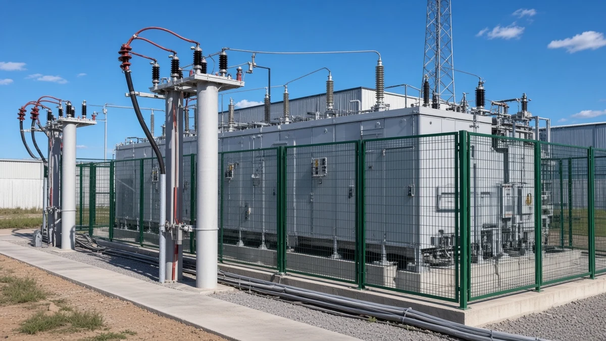
What the Money Actually Buys: The Advantages That Survive Scrutiny
Three benefits survive scrutiny and a fourth is purely commercial: the bank clears a power-factor or kVA demand charge, hands back transformer and cable capacity, props up voltage at the weak end of a circuit, and delivers all of that more cheaply per kvar than anything with electronics in it.
Reactive power (kvar) is the part of the supply that performs no work. It magnetises the iron in motors and transformers, and the plant hands it back every cycle; a shunt capacitor bank supplies that exchange on site so the network upstream stops carrying it.
Usually the invoice triggers the purchase. Where the utility bills a poor power factor or meters kVA demand, making the reactive component locally removes that charge, and no other class of compensation removes it for less money per kvar.
Transformer and cable capacity release is the benefit that holds up best, because you can measure it in amps. The reactive current stops crossing the transformer and the feeder cables, and the capacity it was occupying comes back for load you have not bought yet.
On a long or weak circuit, end-of-feeder voltage support shows up as recovered volts at the far end.
Capacitors are also the cheap, coarse reactive block buried inside much more expensive equipment. In a thyristor-based compensator they still supply the bulk of the vars while the electronics supply speed and smoothness, so the gap between the two price tags is mostly the price of speed.
Resonance: How a Bank Turns Harmonics You Already Have Into Damage
Capacitors generate no harmonics of their own, but they do move the frequency at which the network rings. Let that frequency settle on an order the plant is already making, and the circulating current becomes many times what the load itself injects.
Open a correction cabinet on a drive-heavy site and the evidence is usually waiting: capacitor cans that have swollen, fuse holders that have been reloaded more than once, and wiring discoloured by heat. Those are the capacitor bank problems that get reported, and they are the visible end of something that began on the busbar.
Harmonic resonance arrives when the capacitive reactance of the bank and the inductive reactance of the supply cancel each other at a harmonic frequency. The impedance seen by the harmonic source becomes very large at that point, and the current shuttling between the bank and the transformer is multiplied well past what the load is producing.
Position decides how sharp the multiplication is. A distribution feeder gives the resonant circuit plenty of damping; the secondary bus of a large step-down transformer gives it very little, which makes the identical bank far more dangerous in the second location than in the first.
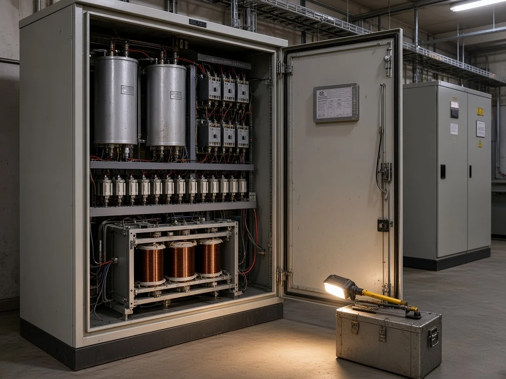
Six-pulse drives are the common source, and practitioners associate them with heavy current distortion at the fifth and seventh orders. A few hundred kvar of plain capacitors on an ordinary plant transformer tends to put the resonant point uncomfortably close to the fifth harmonic, which is why drive-fed buses are where the trouble concentrates.
From the field: the first evidence of capacitor bank harmonic resonance is physical rather than a waveform — swollen cans, fuses that keep operating and scorched wiring inside the correction cabinet, as installing contractors report after fitting switched correction into buildings full of six-pulse drives.
The decision this cost forces is an ordering decision, taken long before the first failure. A detuning reactor in series with each step moves the branch clear of the order that dominates, and where a measured spectrum already shows one order in charge, tuned filter branches are the purchase that answers it.
Light Load: The Night the Bank Is Still Correcting a Plant That Went Home
A bank behaves as a fixed impedance rather than as a controller, so under light load it keeps delivering the vars it was sized for. The bus voltage climbs, the meter starts reading leading, and the asset that paid for itself at midday spends the small hours working against the plant.
Two lines are down for the night, the compressors are idling, and the correction cabinet is still connected with most of its steps in circuit. Nothing has failed; the bank is doing exactly what it was built to do, which now happens to be more than the site is asking for.
Surplus capacitive kvar reverses the net reactive flow. Voltage on the bus rises, the meter records a leading power factor, and the plant starts collecting nuisance trips, warm capacitor cans and switching wear on behalf of machinery nobody is running.
The costlier version of the same story is a bank that was the wrong buy from the first day. Displacement power factor comes from the phase shift of the fundamental current, distortion power factor comes from harmonic content, and capacitors act on the first of those alone.
So a poor reading caused by chopped-up waveforms barely moves when capacitors are connected, while the resonance exposure arrives on schedule. The meter reading has to be split into its two parts before anyone signs for kvar.
What removes the cost is either control or a smaller commitment. An automatic bank drops steps as demand falls away, a target slightly on the lagging side is easier to live with than unity, and a fixed block belongs only on a plant whose reactive draw hardly moves across the day.
Step Granularity: Why a Bank Sized for Full Production Is the Wrong Size Most of the Day
A bank can only follow the plant in the size of the blocks it was assembled from. Run the site at half load and you get either more correction than the load wants, or a step that cycles all shift to avoid exactly that.
An engineer running a bank on a switchgear line-up beside two soft starters framed the difficulty as a contradiction he could not resolve. The bank has to be off while a starter ramps its motor, yet it corrects a great deal more than those two machines, so it also has to stay connected — with fewer stages in — while they sit idle.
That contradiction is granularity, and quotations rarely mention it. Resolution comes from how many switchable groups the bank was built from and how large each group is, which is why a bank correctly sized for full production is the wrong size for most of the working day.
Start-and-stop duty turns the mismatch into wear. Each over-correction the controller avoids costs a switching operation, and a plant whose big drives cycle through the shift can drive its steps through far more operations than the capacitors were bought to see.
Every one of those operations is a disturbance in itself, and the timing of closure has its own engineering literature — point-on-wave switching sets out what that timing buys. Closing a step onto a bus where other steps are already live adds a sharper back-to-back inrush again, which the switchgear has to absorb.
Granularity stays fixed at order time and awkward to change afterwards. More and smaller steps buy resolution and pay for it in switching devices; fewer and larger steps are cheaper and blunter, and a reactive demand that moves faster than contactors can follow has already left this class of equipment.
Fuses, One Failed Unit, and What the Rest of the Bank Does Next
The first failure is normally a fuse or a single capacitor unit, and what happens after it was settled at order time. One fusing scheme keeps the plant running with a lopsided bank; the other eventually makes you replace the whole set.
Two quotations for the same kvar can differ on a single line — internally fused or externally fused — and buyers routinely treat that line as a detail. It becomes the most expensive line in the quotation on the day a unit lets go.
An internally fused bank is straightforward to maintain, but single units cannot be swapped out. Once enough elements inside it have failed, the bank gets changed as a whole rather than repaired.
An externally fused bank stays in service after a fuse clears and the faulty unit can be found by eye. The price is asymmetry: one blown fuse leaves the bank unbalanced even while every remaining unit is perfectly healthy.
The destructive case is separate from both. When a unit fails internally, the healthy units paralleled with it dump their stored energy into the fault, and occupational-safety records describe that as frequently ending in an explosion, which is the reason parallel units are individually fused wherever it can be arranged.
How the units and strings are arranged decides how far that energy can travel, and the forms in service are set out in the piece on series and parallel connection inside a bank.
Treat the fusing scheme as a purchase question, then. Ask what one failed unit does to the remaining capacity, how the unbalance is detected when it happens, and who is expected to find the blown fuse.
Derating: Why the Usable Kvar Is Below the Nameplate
Harmonic current, ambient temperature and altitude all consume the same thermal margin. The kvar a bank can hold in service therefore sits below the figure on the plate whenever the room is hot, the site is high, or the waveform is distorted.
The environmental block on a compensation data sheet reads like boilerplate until you check it against the room the equipment is going into. The HYFC Series filter compensation device states its own envelope plainly: ambient −25 °C to +40 °C, relative humidity ≤90% at 20–25 °C, altitude ≤1000 m with derating required above that, and a permitted supply variation of −10% to +10%.
Each of those lines is a limit on how much heat the equipment can shed, and an ordinary indoor substation in summer can breach more than one of them at once. Ventilation, filter cleanliness and cabinet spacing decide which.
Harmonic current belongs on that same list. To a capacitor it arrives as heat, which is the currency the ambient limit is written in. Elevated current ages the dielectric early and ends the unit's life sooner than its rating implies, so a distorted bus quietly shrinks what was bought.
Nameplate kvar is therefore the figure you order; the figure you keep is smaller. On a hot, high or distorted installation the usable capacity has to be derated while the order is still open, or the shortfall turns up during the first hot spell.
Maintenance and Stored Charge: The Recurring Cost of Ownership
What arrives on site is a populated cabinet — contactors, fuses, a control relay, a control transformer and ventilation fans — and every visit to it opens with a discharge and a visible ground. A bank that has been switched out still holds a charge, and it can rebuild one without any source connected to it.
A maintenance visit therefore begins some minutes before anyone touches hardware. The bank is isolated, drained through its bleeder path and its discharge device, then tied to a grounding point that the technician can actually see, and only then does the booked work start.
Important: a de-energised bank still holds a hazardous charge and can recover one with no external source at all — so grounding comes before contact every time, and earthing a single point of a series string can transfer the charge rather than remove it.
Occupational-safety practice attaches figures to that procedure: the bank must fall below 50 V within 5 minutes of isolation, and above 5 J of stored energy an automatic discharge device has to act when an access port is opened.
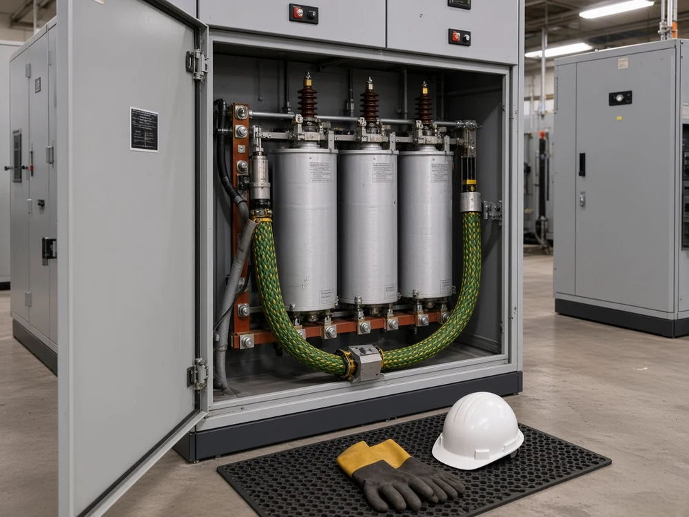
The capacitors are only part of what gets serviced. Contactors wear, fuses are consumed, ventilation fans and filters clog, and the control relay is an electronic item with a life of its own. The spares list for a correction cabinet ends up longer than most buyers expect.
A failed unit is a housekeeping problem as well as an electrical one, because the liquid dielectric inside the can, and anything it produces while burning, can be toxic.
None of this looks exotic, and all of it recurs. It belongs in the operating budget as an annual visit, a stock of fuses and contactors, and time on every single visit for the discharge that has to come first.
Fixed or Automatically Switched: Which of These Costs You Inherit
These are two different purchases. A fixed bank inherits the light-load costs and none of the control costs; an automatically switched bank trades those away and takes on switching duty, contactor wear and a controller that is only ever as good as its current signal.
Published lists of the disadvantages of capacitor bank in power system contexts almost never say which of the costs a particular site will actually inherit. Sorted by fixed vs automatically switched bank, most of them land clearly on one side.
| Cost | Fixed bank | Automatically switched bank | What the site meets first | Mitigation or the cue to buy differently |
|---|---|---|---|---|
| Harmonic resonance | Inherited from the moment it is energised | Inherited, and across more steps | Swollen cans, repeated fuse operation, scorched wiring | Detuned reactor / detuning chosen from a study, or tuned filter branches |
| Leading power factor / overcompensation | The principal cost it owns | Largely handled by the controller | Rising bus voltage and a leading meter on quiet shifts | Automatic stepping, or a fixed block only where the load barely moves |
| Step granularity / switching steps | Absolute: one block, in or out | Limited by step size and step count | Correction that overshoots, or a step that cycles all shift | More and smaller steps agreed at order time against the load profile |
| Capacitor switching transient | Once per manual operation | Every controller decision, all shift | Voltage steps felt by sensitive equipment on the same bus | Controlled energisation timing, or compensation that changes without switching |
| Capacitor fuse / unbalance | Inherited | Inherited, step by step | A blown fuse and an unbalance alarm | Fusing scheme and unbalance detection settled in the quotation |
| Cascading unit failure / capacitor explosion | Inherited | Inherited | A ruptured can and collateral damage inside the cubicle | Individual fusing of paralleled units |
| Derating (harmonic and thermal) | Inherited | Inherited | A hot cabinet and units that fail early | Envelope and harmonic duty checked against the actual room before ordering |
| Stored charge / discharge procedure | Inherited | Inherited | Nothing visible at all, which is precisely the hazard | Bleeder path, discharge device and a visible ground on every visit |
| Automatic power factor correction (APFC) controller and CTs | Never inherited | Inherited exclusively | Correction held at the wrong target, or a stage stuck in circuit | CT ratio, polarity and position proved at commissioning |
The last row is where switched banks surprise owners. A welded contactor leaves a stage energised whatever the controller commands, and a current transformer with the wrong ratio, reversed polarity or the wrong position leaves the controller correcting a plant it cannot see.
Fixed banks have a surprise of their own, and it usually belongs to somebody else's project. A site can run an unfiltered fixed block for years and then start losing fuses the month a new drive-fed machine is commissioned next door.
Which column you end up in is decided by four order-time choices: the reactor ratio, the protection method, the connection form, and fixed or automatic switching. All four are taken from the system voltage, the harmonic conditions and the capacity required, across the high-voltage power factor compensation series rather than after commissioning.
Position shifts the weighting again, and the map of where a bank belongs on the network covers that separately.
What to Measure Before You Order
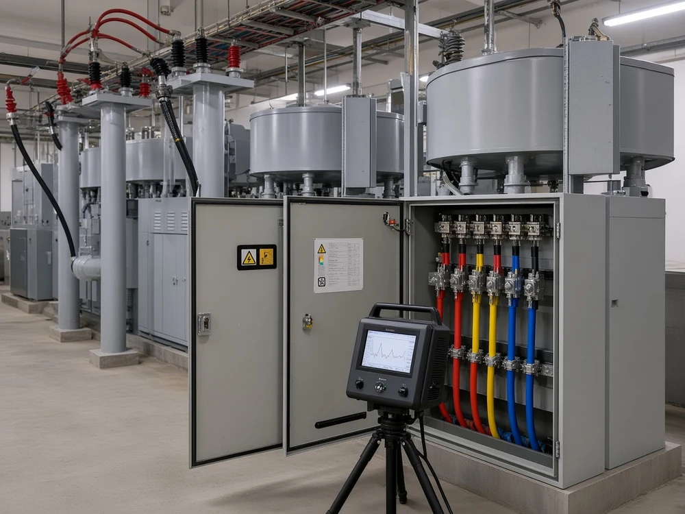
Six measurements separate a bank that pays for itself from one that causes work. Take them before the order goes out, because every one of them changes what should be quoted.
Suppliers who ask for these numbers are not being difficult. Reactive power (kvar) is the thing being bought, and each measurement sets a bound on how much of it a particular bus can absorb without complaint.
| What to measure | Why it decides the purchase | What the answer changes |
|---|---|---|
| Harmonic voltage and current spectrum at the bus that will carry the bank (THDi / THDv), with the non-linear load share on that transformer and the system short-circuit power / source impedance behind it | Existing distortion is what a plain bank amplifies, and these three inputs place the resonant point | Plain bank, detuned bank, or a harmonic filter (tuned filter branch) |
| Load profile across a full production cycle, nights and weekends included, and what moves it (arc furnace / rolling mill / welding and VFD loads) | The light-load hours are when a fixed block overcorrects | Fixed or automatic, and how many steps |
| Present power factor and the tariff clause behind the bill (kVA demand billing / power-factor penalty) | Fixes what the correction is actually worth | Whether the project clears its cost at all |
| Bus voltage behaviour when the plant is quiet | Shows the headroom left before correction pushes voltage up | Step size, and the controller target |
| Room temperature, ventilation and site altitude | Thermal margin is consumed before the bank does any work | Derated capacity, cabinet rating and cooling |
| CT ratio, polarity and position, and where the controller is told to sense | A blind controller corrects the wrong thing confidently | Commissioning checks, and sometimes the CT itself |
Tip: the condition that decides the whole purchase is measurable before the order goes out — log the common bus and count how much of the transformer's load is drives and rectifiers before anyone specifies plain capacitor steps.
How much correction to buy is a separate calculation from whether to buy it, and the arithmetic is set out in the piece on sizing a bank for power factor correction.
A survey that covers these six is short work for a competent contractor, and it is the cheapest part of the project. Skipping it moves the same investigation to the weeks after commissioning, when the bank is already in the cubicle and the cost of changing the answer is the cost of buying twice.
When the Cost Side Wins: The Loads a Switched Bank Cannot Serve
Some duties defeat a switched bank by definition. Where the load changes faster than contactors can follow, where distortion rather than displacement is the real problem, or where the constraint is energy instead of reactive power, more steps and a better controller will not rescue the purchase.
Welders, arc furnaces, hoists and large drives swing their demand in seconds or less. A stepped bank answers in the time it takes a controller to decide and a contactor to close, so it spends the shift chasing a target that has already moved, and the mechanical wear is charged to the owner while the disturbance the plant complained about is still there. Furnace and rolling-mill duty is the clearest example, and it is treated as its own class of problem in the steel and metallurgy power quality solution.
Distortion-dominated buses are the second case. If the spectrum is the reason the power factor looks poor, adding plain capacitance treats the symptom and feeds the cause; the equipment that belongs there filters rather than merely compensates, and the measurement has to be taken at the bus that will carry it, which is how a plant-wide power quality solution is scoped.
Dynamic and storage equipment begin at that boundary. A static var generator, or SVG / STATCOM equipment, responds in electronics time instead of contactor time and suits fast, fluctuating loads; battery energy storage addresses a different problem again, because it supplies energy rather than correcting the phase relationship, and no capacitor bank of any size does that. Each of those is a separate purchase with its own economics, and treating them as interchangeable with a bank is how projects end up with the wrong equipment in the right cubicle.
Recognising the boundary early is cheaper than discovering it. If the load profile is violent, the spectrum is heavy, or what the site actually lacks is energy, the honest answer is that a switched bank is the wrong instrument and the budget should go elsewhere.
How to Choose Filter Compensation When the Measurements Say a Plain Bank Would Ring
When the survey comes back showing significant distortion, the purchase changes shape and not size. The same kvar still has to arrive, but it now arrives through branches tuned to the orders that were measured, and tuned branches absorb those harmonics instead of amplifying them.
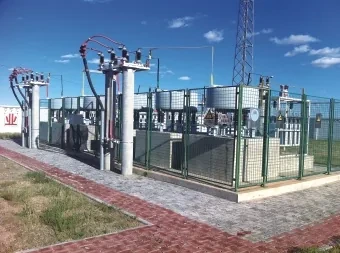
That is the job the HYFC Series high voltage passive filter compensation device is built for: tuned reactor-capacitor branches that absorb selected harmonic orders while supplying reactive power on 6 kV to 66 kV systems, with tuning frequencies available from the 2nd, 3rd, 4th, 5th, 7th, 11th and 13th orders and above.
Each branch is configured from the measured harmonic spectrum, the load demand and the grid impedance. The survey in the previous section therefore has to be finished before the quotation goes out, not repeated after it.
Tuning stays fixed when the device is built. A plant part-way through changing its drive population should finish that change first, or accept a configuration matched to the load it had at order time.
The published envelope is part of the specification too, so hot rooms, high sites and wide supply variation all have to be declared up front. Usable capacity is derated against them, and nobody can design around a condition they were not told about.
If the measurements point this way, read the product overview and send three things: the system voltage, the capacity you need, and the logged spectrum and distortion figures from the common bus. With those in hand the branches can be tuned to the orders your plant actually produces.
FAQ
Does a capacitor bank consume energy?
Not in the sense the bill cares about. A bank exchanges reactive power with the load instead of doing real work, so what it changes is the reactive component of the supply and the charges attached to it, not the plant's production of useful output. It has small internal losses of its own, like any piece of connected equipment, and those are a cost of ownership rather than the point of the purchase.
Can capacitor banks cause harmonic distortion or resonance?
Resonance yes, distortion no. Capacitors do not generate harmonics — rectifiers, drives, furnaces and other non-linear loads do that — but a bank changes the frequency at which the network rings, and that is enough to magnify distortion that was already present and previously tolerable. It then suffers from the result, because the magnified current flows through the capacitors themselves.
How do I know whether my site will have a resonance problem before I buy?
By measuring, which is the only honest answer. Log the harmonic spectrum on the common bus that will carry the bank, establish how much of that bus is drives and rectifiers, and obtain the supply's short-circuit strength from the utility, because those three inputs together decide where the resonant point lands. A supplier who quotes tuned or detuned equipment without asking for them is guessing.
Do capacitor banks need maintenance, and is a de-energised bank safe to touch?
Yes to the first, and firmly no to the second. The cabinet contains contactors, fuses, a control relay and ventilation that all wear, so an annual service scope is reasonable; and a bank that has been switched out retains a hazardous charge and can rebuild one on its own, so every visit starts with discharging it and fitting a ground the technician can see.
What is the lifespan of a capacitor bank, and what shortens it?
No single figure is worth quoting, because service life depends almost entirely on duty and environment. What shortens it is specific and measurable: harmonic current heating the dielectric, a hot or poorly ventilated cabinet, altitude and ambient conditions outside the declared envelope, sustained overvoltage from overcompensation, and repeated switching wearing the contactors. A bank running inside its envelope on a clean bus ages slowly; the same bank on a distorted, hot, overcorrected installation does not.
Is a capacitor bank better than an SVG?
They answer different duties; the comparison only means anything site by site. The speed of the reactive swing is the deciding factor: mechanically switched capacitance suits loads that change over minutes and shifts, while loads that swing by the second need equipment that responds without waiting for a contactor. Cost follows that split, and so does the maintenance scope.
What happens if the power factor goes leading at night?
The bus voltage drifts up and the charges can move the wrong way. Two consequences are easy to miss: a site with its own generating plant can find that generation less stable against a leading bus, and some tariffs treat a leading reading as a deviation of its own, so the correction that cleared one charge can introduce another. Confirm it before rebuilding anything — log a full quiet shift, check which way the reactive flow goes, and then decide between dropping steps automatically and buying a smaller fixed block.
References
- Capacitors — institutional safety practice for stored charge: residual voltage after isolation, bleeder and discharge requirements, series-string grounding, cascading failure of paralleled units, and dielectric hazards.
- Impact of harmonics in a distribution network after capacitor bank placement — an independent engineering study of how adding capacitance shifts the resonant point and magnifies harmonics that the network already carried.
- Power factor — why reactive compensation is bought at all, the difference between displacement and distortion power factor, and what happens when correction is left connected at light load.
- Static VAR compensator — where electronically controlled compensation takes over from mechanically switched capacitor banks on fast-swinging loads.
- Power factor correction and harmonic resonance — practitioners describing detuned steps, sites that started losing fuses after new drive-fed equipment arrived, and the habit of logging the bus before accepting a diagnosis.
- What's the real problem having a PF correction capacitor bank on the same bus as soft starters? — engineers working through what a bank shares a bus with, and why the neighbouring load matters more than the bank's rating.
- Why do power harmonics matter? — community explanation of harmonic heating, and why distorted current shortens component life instead of merely confusing a meter.