
 Zhejiang Hongyan Electric Co., Ltd.






































The reactive power formula in 3 phase work is Q = √3 × V_LL × I_L × sin φ on a balanced feeder. If the board already shows kilowatts and power factor, the matching path is Q = P × tan(arccos PF). The sections below sort those inputs, keep line-to-line voltage from being mixed with line-to-neutral, run labeled educational arithmetic, and show when a computed kvar points at a high-voltage shunt bank.
Pick the formula from the quantities you actually have. A three phase reactive power formula is not a different definition of Q; it is the same quadrature quantity with the √3 geometry already folded into line values.
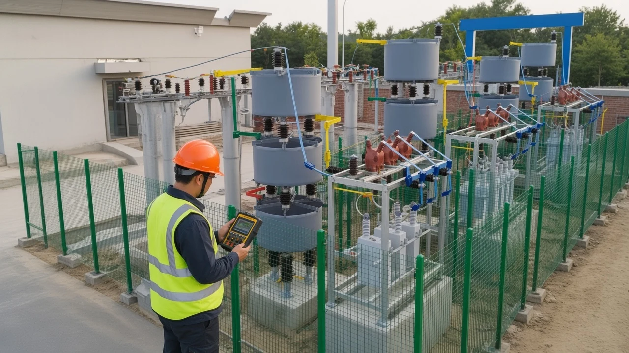
The Three-Phase Formula: Q = √3 × V_LL × I_L × sin φ
For a balanced three-phase system, Q is √3 times line-to-line RMS voltage, line current, and sin φ. φ is the phase angle between phase voltage and phase current, not the angle a casual clamp might invent between a line-to-line voltage and a line current.
Independent formula sheets write the same identity as Q = √3 V_LL I_L sin φ, with S = √3 V_LL I_L and P = √3 V_LL I_L cos φ (Atlas of Engineering AC power formula sheet). Encyclopedia AC-power pages keep Q as the quadrature leg: Q = |S| sin φ and |S| = √(P² + Q²) (Wikipedia article on AC power).
Reactive power is that quadrature component. It does not deliver net work over a cycle, but the current that carries it still heats conductors and occupies transformer capacity.
Units stay in var, kvar, or Mvar. Under the common load convention, lagging current is positive Q.
| Available inputs | Three-phase Q formula | Notes |
|---|---|---|
| V_LL, I_L, φ | Q = √3 × V_LL × I_L × sin φ | Balanced; φ is phase V vs phase I |
| kW and PF | Q = P × tan(arccos PF) | Same interval; sinusoidal displacement PF |
| kVA and PF | Q = S × sin(arccos PF) | Same as S × √(1 − PF²) |
| kVA and kW | Q = √(S² − P²) | One signed total, not mixed leading plus lagging kVA |
√3 is about 1.732. Dropping it on a balanced line-value calculation understates Q by that factor.
Line Values Versus Phase Values
Phase form is 3 V_ph I_ph sin φ; the √3 form already wants line quantities. Once you use line-to-line volts and line amps, wye / delta share the √3 formula.
In a balanced wye, V_LL = √3 V_ph and I_L = I_ph. In a balanced delta, V_LL = V_ph and I_L = √3 I_ph. Either pairing collapses to the same line-value expression.
The √3 form already expects line-to-line voltage. Feeding a line-to-neutral reading into that identity cuts the answer by about 1.732. A calculator FAQ on three-phase power makes the same point and tells the user to enter line-to-line, not line-to-neutral (Calculator Academy three-phase power calculator).
Important: On a 400 V three-phase label, 400 V is the line-to-line voltage (Calculator Academy three-phase power calculator). The line-to-neutral figure is about 231 V. Put 231 V into the √3 formula and the kvar comes out too low by √3.
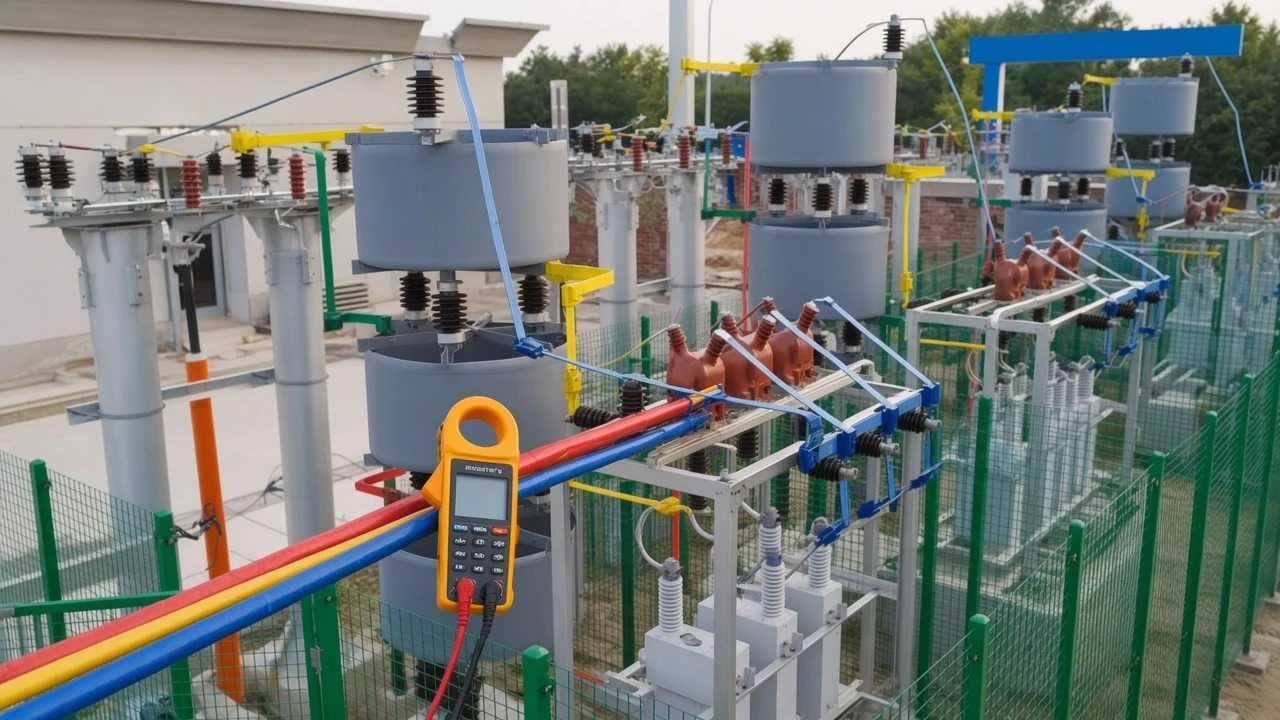
Connection type still matters for protection and unit arrangement. It does not invent a second line-value Q formula.
Reactive Power Formula with Power Factor
If you have kW and power factor, Q = P × tan(arccos(PF)). That is the reactive power formula with power factor when the PF is a sinusoidal displacement reading from the same interval as the kilowatts.
Atlas writes the identity as Q = P tan(cos⁻¹ PF) and tells the reader to take the sign from load type or phasor reference, not from the magnitude alone (Atlas of Engineering AC power formula sheet). Use the decimal PF (0.87), not 87, inside the inverse cosine.
The same path rearranges from PF = P / S. Then sin φ = √(1 − PF²) and Q = P × (√(1 − PF²) / PF). Both routes should agree on a clean sine-wave board.
A wattmeter-style real-power channel plus a compatible PF is enough for this path. You do not need a separate phase-angle display if the meter already computed PF from the same samples.
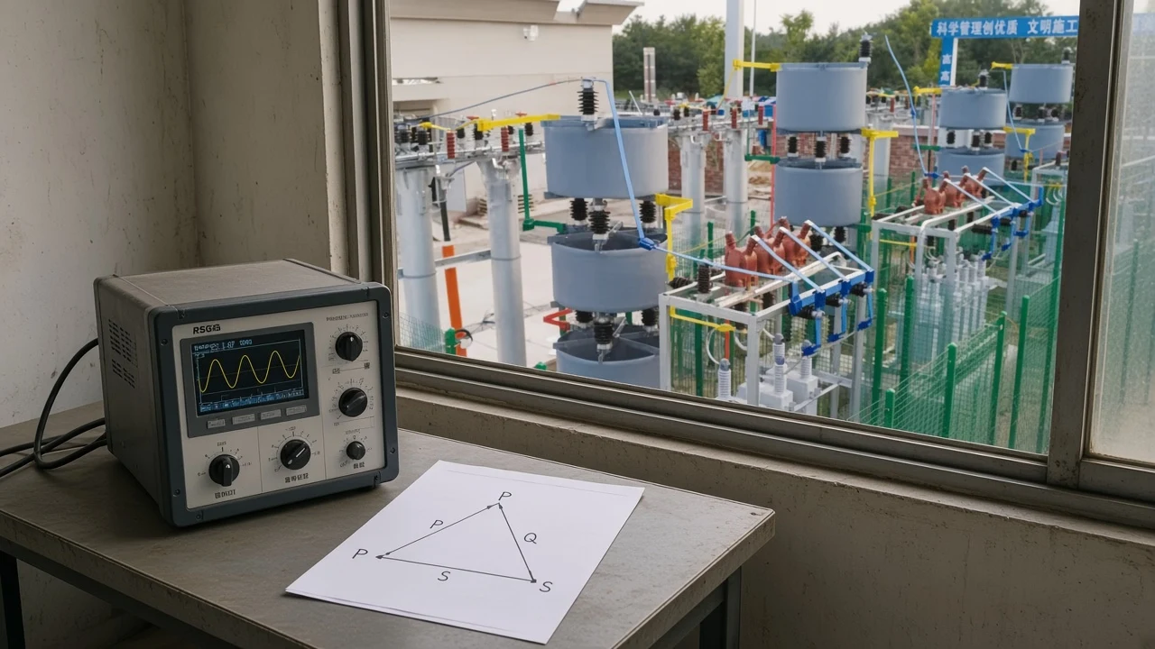
From kVA and the Power Triangle
If you have kVA and PF, Q is S times sin of the PF angle. Write Q = S × sin(arccos PF), or Q = S × √(1 − PF²).
When the triangle applies, Q is the other leg of √(S² − P²). Electrician-forum arithmetic states the plant form as kVAr = √(kVA² − kW²) after PF = kW / kVA (Mike Holt Forum thread on kVA/kW calculations).
Compute Q per load, keep the sign, then add. A Mike Holt study thread on calculating reactive power warns that Q_total = √(S_total² − P_total²) fails when one load is lagging and another is leading: apparent powers do not add the way P and signed Q do (Mike Holt Forum thread on calculating reactive power).
Active power and apparent power still have to share one metering interval. Mixing last week’s kW with this morning’s kVA invents a triangle that the bus never saw.
Worked Three-Phase Examples
Run labeled educational math for the 400 V / 0.87 and 13.2 kV / 30° cases. These are worked arithmetic from stated inputs, not logged readings from a named plant.
| Example | Stated inputs | Path | Result |
|---|---|---|---|
| A — V, I, PF | 400 V line-to-line, 100 A, PF 0.87 | Q = √3 × V × I × sin(arccos 0.87) | Q ≈ 34.2 kVAR |
| B — V, I, angle | 13.2 kV, 60 A, φ = 30° | Q = √3 × 13.2 × 60 × sin 30° | Q ≈ 686 kvar |
With 400 V line-to-line, 100 A, and PF 0.87, Q is about 34.2 kVAR. The same stated inputs give P ≈ 60.3 kW and S ≈ 69.3 kVA on the published calculator walkthrough (Calculator Academy three-phase power calculator).
Using 13.2 kV, 60 A, and 30°, Q = √3 × 13.2 × 60 × sin 30° ≈ 686 kvar. Those voltage, current, and angle figures are the default inputs printed on a three-phase reactive-power calculator; the arithmetic itself uses the Atlas line-value identity and is labeled educational, not a field measurement.
sin 30° = 0.5, so example B is half of √3 × 13.2 × 60 ≈ 1,372 kVA. PF at 30° is cos 30° ≈ 0.866, which is why a nearby PF-0.87 case looks similar on paper.
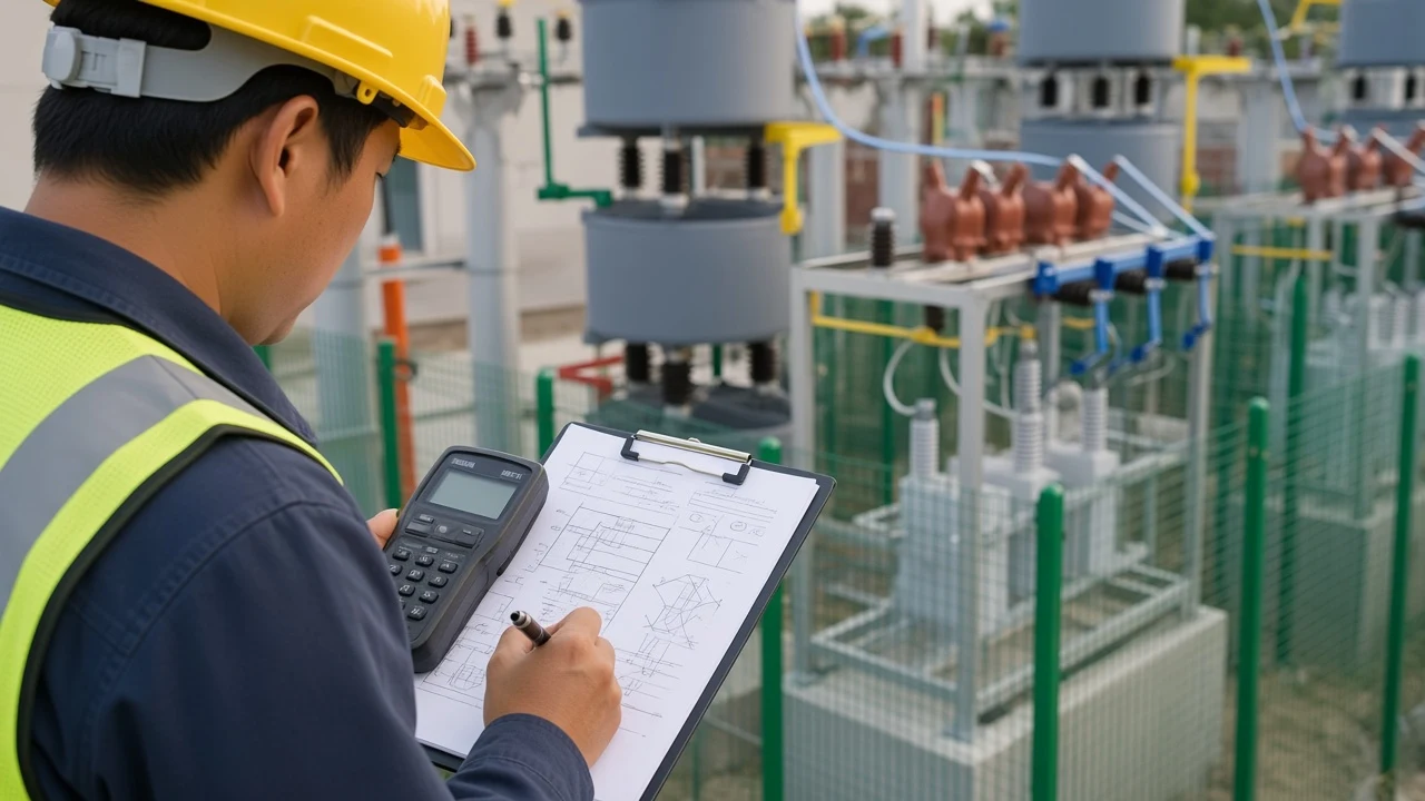
Required capacitor kvar to move from one PF to another is a later step. Qc / kvar bank sizing uses Qc = P × (tan φ1 − tan φ2). Open the sibling guide on how to calculate kvar for capacitor bank after present Q is known.
When One Snapshot Is Not Enough
If phases disagree, compute each phase and add Q. Atlas writes the unbalanced screen as Q_total = Σ V_i I_i sin φ_i and says the balanced formulas are not valid unless each phase is analysed separately (Atlas of Engineering AC power formula sheet).
Instrument write-ups on three-phase power make the same summing point: Q_total = Q_A + Q_B + Q_C, and a line-to-line voltage must be converted before it is paired with a line current. A single √3 snapshot on one CT is a shortcut, not a substitute for analyzer totals on a skewed board.
Under distortion, a sin φ reading is not the whole reactive story. Forum notes on kVA/kW calculations add that capacitors correct the displacement portion of non-unity power factor, not the portion due to harmonics (Mike Holt Forum thread on kVA/kW calculations).
Displacement vs distortion therefore changes which Q you trust. Keep voltage, current, and real power simultaneous at the same electrical boundary.
Which HYTBB Fit After You Compute Three-Phase Q
A known HV kvar demand can fit a 6–35 kV shunt frame; Qc sizing is a later step. After the three-phase formula has produced a present Q, the hardware question is whether a shunt capacitor bank should supply that capacitive kvar on a medium- or high-voltage bus.
The HYTBB Series High-Voltage Reactive Power Compensation Device – Outdoor Frame Type is a 6–35 kV shunt capacitor bank selected from required kvar. Shunt capacitor compensation on that device is chosen from system voltage, harmonic conditions, and required capacity, with fixed or automatic switching.
Published ratings include 150–10,000 kvar at 10 kV and below. The same specification table lists 600–20,000 kvar at 35 kV, 50–60 Hz, and single capacitor units from 50–500 kvar.
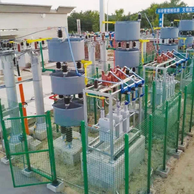
Browse the High Voltage Power Factor Compensation Series when the bus needs a frame bank, a pole-mounted unit, or a faster TSC / SVC option. Fast-swinging mills and hoists often belong on a thyristor-switched or dynamic device rather than a stepped outdoor frame.
Required capacitor kvar is a separate step after you know present Q. This page does not invent listings, SKUs, or payback; it stops at the formula and the printed HYTBB range.
If power factor itself is the missing input, calculate it first from kW and kVA, then return to the PF path above. The companion procedure is how to calculate power factor when that URL is the live sibling.
FAQ
What is the reactive power formula in a 3-phase system?
For a balanced three-phase system, Q = √3 × V_LL × I_L × sin φ. φ is the angle between phase voltage and phase current.
How do I calculate reactive power from voltage and current?
Use line-to-line RMS voltage and line current in Q = √3 × V_LL × I_L × sin φ. Convert φ from a compatible PF with φ = arccos(PF) when the board gives PF instead of an angle.
If I already have kW and PF, how do I get kvar?
Use Q = P × tan(arccos PF) with decimal power factor and kilowatts from the same interval. Check the result against Q = S × √(1 − PF²) if kVA is also on the display.
Is the 3-phase formula different for star and delta?
The line-value formula is the same. Wye and delta change how phase voltage and phase current relate to line quantities; they do not create a second √3 identity.
Can I use Q = √(kVA² − kW²) for mixed loads?
Use it on one load, or on one signed total. If one feeder is lagging and another is leading, compute each Q, keep the sign, then add.
Does a leading power factor make Q negative?
Under the common load convention, yes: lagging / inductive Q is positive and leading / capacitive Q is negative. State the convention before you add banks and motors on one drawing.
How to calculate PF in 3-phase?
PF is still P ÷ S. On a balanced feeder, S = √3 × V_LL × I_L, then PF = P ÷ S. That calculation is the sibling job; this page uses PF as an input to Q.
What is the formula for required kVAR?
Required capacitor kvar to change PF is Qc = P × (tan φ1 − tan φ2). That is the sibling sizing page, not the three-phase Q identity used here.