
 Zhejiang Hongyan Electric Co., Ltd.
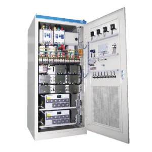
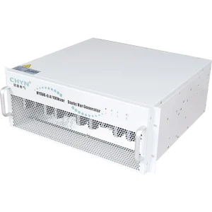
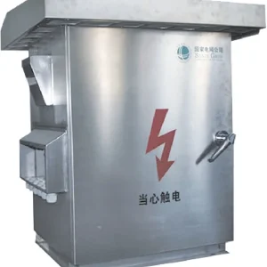
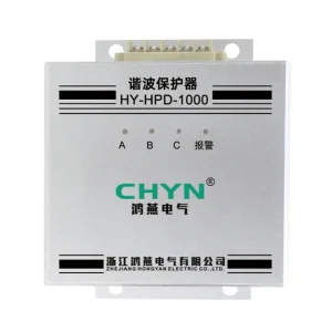
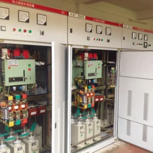
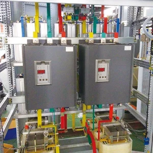
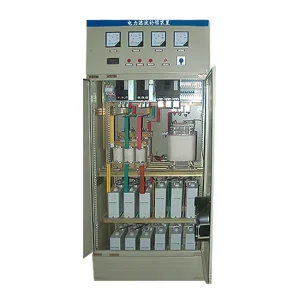
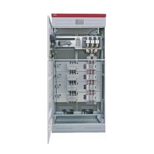
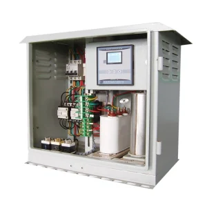
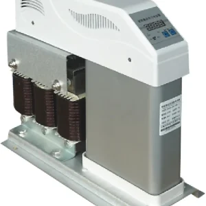
Static var generator CT polarity should be verified together with phase assignment, voltage reference, CT ratio and measurement location before automatic compensation is released. A plausible current reading does not prove that the controller sees the correct direction of reactive power. Start from the approved drawing and the selected SVG manual, compare measurements against an independent reference, then test an approved limited response. If compensation moves in the wrong direction, stop and resolve the measurement chain. This guide defines the evidence to request; it is not a generic terminal-wiring instruction.
Define what the controller is supposed to measure
A current transformer supplies a scaled current signal. The controller interprets that signal in relation to its voltage inputs and configured measurement arrangement. Before inspecting polarity, mark the intended measurement boundary on the single-line diagram. Identify whether the sensors represent supply current, load current or another approved arrangement. Include the SVG connection point and any other compensation equipment.
That boundary can change meaning when bus ties, parallel transformers, generators or photovoltaic sources are involved. A CT may be physically correct yet measure only part of the current relevant to the control objective. Ask the design team to list the permitted switching states and the current path in each. A sign correction in software cannot bring an unmeasured feeder inside the measurement boundary.
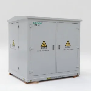
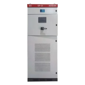
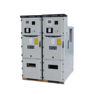
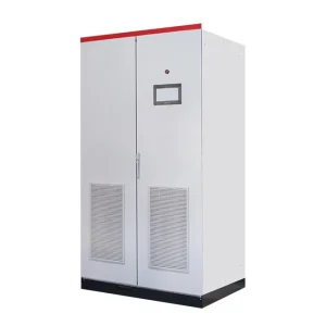
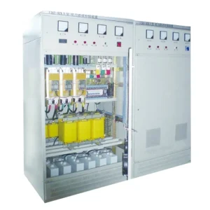
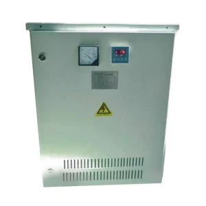
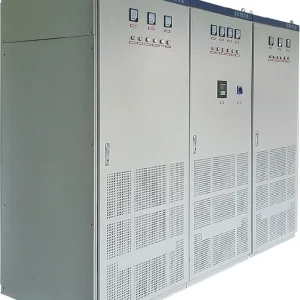
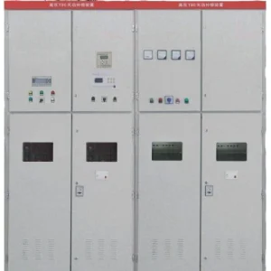
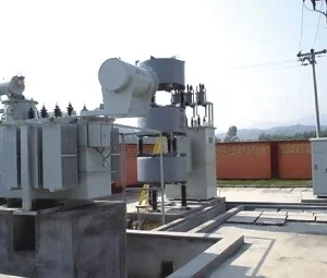
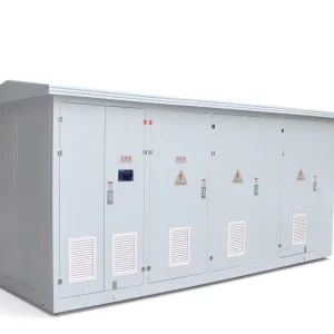
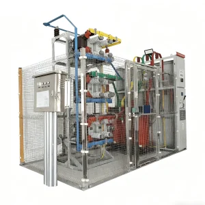
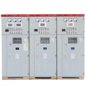
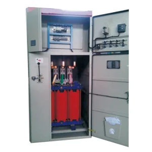
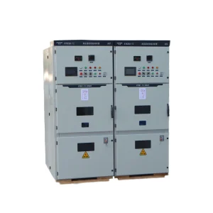
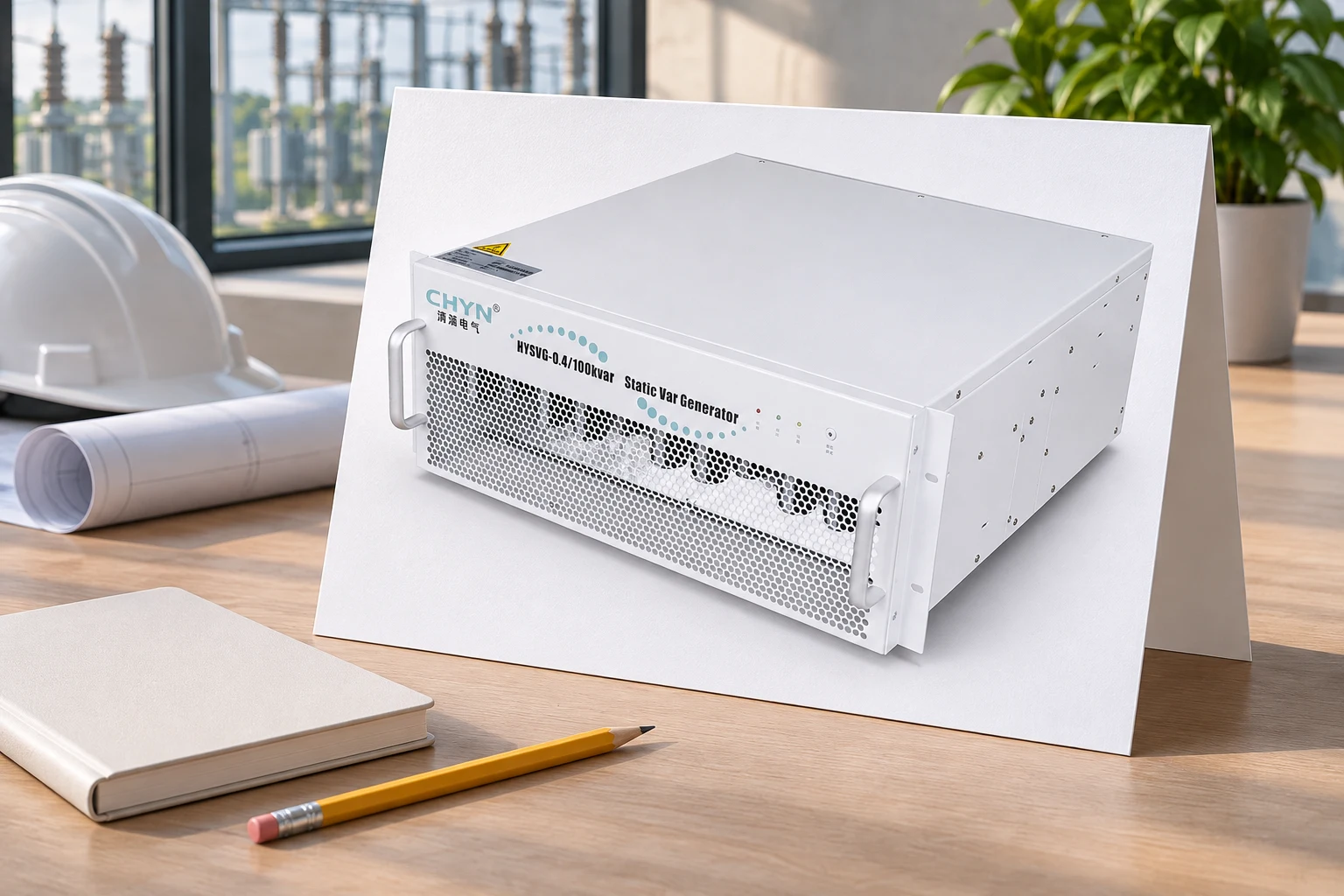
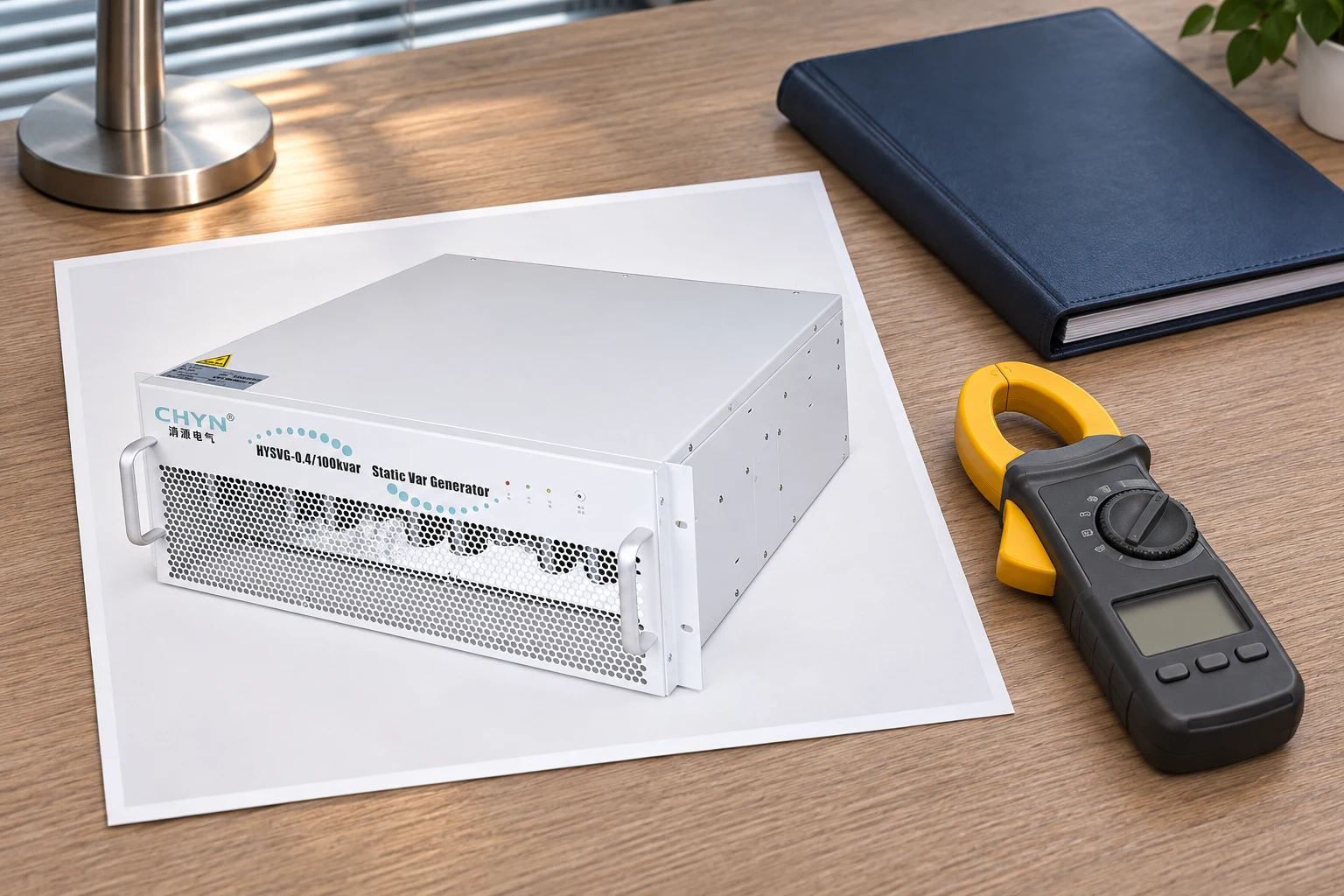
The CHYN HYSVG static var generator is the relevant product family for this discussion. Its public product information describes reactive compensation functions; it does not replace the connection instructions supplied for the selected controller and assembly. Request those instructions and the approved project diagram before specifying CT quantity, location or terminals.
Separate polarity from phase assignment and ratio
Polarity describes the relative reference directions of the transformer windings. Phase assignment describes which current signal belongs with which voltage reference. Ratio describes how the secondary signal is scaled into primary current. These checks answer different questions. Correcting one does not prove the other two, and a total three-phase display can conceal a problem affecting only one phase.
The IIT Madras transformer testing notes explain why winding polarity must be identified for polyphase connections. For an SVG installation, translate that principle into a traceable record from each marked sensor through the secondary circuit to the assigned controller input. Follow the actual CT and controller documentation; terminal colors and naming conventions are not interchangeable across all equipment.
Keep ratio and input-type verification separate from visual direction. Record the selected primary/secondary ratio, connected tap where relevant, controller input specification and configured scaling. Do not assume that changing a numerical ratio setting makes an incompatible sensor output suitable for the input. Obtain written confirmation when the sensor and controller documentation do not establish compatibility.
| Check | Required record | Why a quick glance can mislead |
|---|---|---|
| Measurement location | Marked single-line boundary and permitted source states | Correct readings may represent the wrong feeder |
| Polarity | CT markings and traced secondary reference | RMS current magnitude can remain plausible after reversal |
| Phase assignment | Current channel matched to its voltage phase | Similar phase currents can hide crossed channels |
| Ratio and input compatibility | Sensor rating, connected tap and controller configuration | A believable display value can still be scaled incorrectly |
| Control response | Approved limited test and independent supply-side result | A better displayed power factor alone does not prove correct action |
This checklist identifies evidence, not universal settings. CT count, location, burden requirements and correction options depend on the selected system. The broader static var generator explanation covers the compensation principle; this article focuses on proving the measurement chain before that principle is used in automatic control.
Establish a credible baseline before enabling compensation
With the SVG in the approved non-compensating state, record voltage, current, active power, reactive power and the indicated leading or lagging condition. Note the operating load and the state of other capacitor banks or converters. Use an appropriately connected independent power instrument where the commissioning plan requires it. A baseline without a recorded plant state is difficult to compare with a later result.
Inspect per-phase information as well as totals. An importing site can legitimately export during generation, so negative active power does not automatically prove reversed polarity. Likewise, a leading reactive-power indication may reflect real compensation elsewhere. Reconcile the display with the known operating state before choosing a correction. Avoid trial-and-error swapping until the headline power factor looks satisfactory.
Distinguish displacement power factor from total power factor if the controller exposes both. Harmonic current can affect the latter even when fundamental reactive current changes as intended. The related SVG and active harmonic filter comparison helps keep those duties separate. Do not diagnose every incomplete power-factor improvement as a polarity fault.
Use an approved limited-response test
Agree on a restricted commissioning condition with the supplier and responsible engineer. Define the intended response, permissible limits, independent measurement point and stop conditions before enabling output. Record the before-and-after reactive power and phase currents under a sufficiently stable load. The purpose is to show that the source-side response agrees with the control objective, not to seek a maximum output during an uncertain first test.
If source reactive power moves away from the agreed target, current becomes unexplained, or the response is unstable, inhibit further automatic operation under the approved procedure. Recheck the complete chain: CT location, polarity, phase association, voltage sequence, ratio and control configuration. Several errors can produce superficially similar symptoms. Record the observed result rather than declaring a particular cause before the checks are complete.
After a correction, repeat the relevant baseline and limited-response checks. Changing both wiring and software polarity without tracking each change can obscure what the controller finally receives. Preserve a clear final configuration and remove superseded instructions from the commissioning package. A successful local display check should be accompanied by the independently measured system response required by the project.
Protect the CT secondary during investigation
Do not disconnect a conventional current-output CT secondary while its primary is energized. Dangerous secondary voltage can result. California's current-transformer-secondary safety rule requires avoiding an open secondary while energized and addresses bridging when the primary cannot be deenergized. Its legal scope is jurisdiction-specific; the installation must follow its own applicable rules and approved work procedure.
Polarity investigation is therefore planned electrical work, not a live experiment with loose sensor leads. Qualified personnel must identify the sensor type and use the approved isolation, test and shorting arrangements where applicable. A Rogowski coil, voltage-output sensor and conventional CT need their respective instructions. This article does not authorize applying one sensor's test method to a different input system.
For review purposes, request the completed test records rather than instructing an operator to reverse a pair of leads. Record who performed the work, which drawings were used, what was changed and how the final state was verified. That record is especially valuable after maintenance, because a replacement controller can restore default settings that differ from the accepted commissioning configuration.
Check every normal source configuration before handover
A single successful test on the normal transformer supply does not establish correct behavior with a bus tie closed or a generator supplying selected loads. Use the project's operating-state list. Confirm that the selected controller receives the required measurements in each permitted state, and document any state in which compensation must be inhibited. Keep interlock behavior consistent with the approved switching arrangements.
Coordinate with existing capacitor controllers and other converters. A changing branch can alter reactive demand while a test is underway, making an otherwise correct SVG response look inconsistent. The APFC hunting guide covers a related symptom at system level. It complements this measurement-chain check; repeated switching and incorrect phase reference are not the same diagnosis.
The handover file should contain the final single-line diagram, CT schedule, polarity and phase records, controller settings, baseline measurements, limited-response result and permitted operating states. Include the retest triggers: CT replacement, changed cable routing, controller replacement, software restoration or a revised supply arrangement. Maintenance teams then have a defined reference instead of a note that the system once displayed a good power factor.
Further learning: instrument transformers
The following NPTEL lecture explains current and potential transformers. It provides background for understanding measurement references and scaling. Apply the selected SVG and sensor instructions for the actual installation, and use the lecture as educational material rather than a connection diagram.

Watch Lecture 42: Current transformer and potential transformer on YouTube.
Frequently asked questions
Can normal current readings prove correct CT polarity?
No. RMS current magnitude can appear plausible even when its direction reference is reversed. Verify polarity, phase association and voltage reference using the approved drawings and test records. Then confirm the system response under an approved commissioning condition rather than relying on the current display alone.
Does negative active power always mean a reversed CT?
No. Actual power export can legitimately produce a negative indication under the instrument’s sign convention. Compare the reading with the operating state and independent measurements. Reversed polarity and incorrect phase assignment are possible causes, but neither should be declared before the measurement chain has been checked.
Can I reverse CT wires while the system is running?
Do not improvise live secondary changes. A conventional current-output CT must not be left open-circuited with an energized primary. Qualified personnel must follow the applicable isolation and approved test arrangements for the actual sensor and controller. This guide supplies review criteria, not authorization for live electrical work.
When should the SVG measurement chain be checked again?
Recheck after CT or controller replacement, changed phase routing, restored settings or a revised source arrangement. Preserve the accepted configuration and repeat the affected baseline and response tests. A previous commissioning result applies to its documented configuration and does not establish correctness after later modifications.