
 Zhejiang Hongyan Electric Co., Ltd.
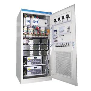
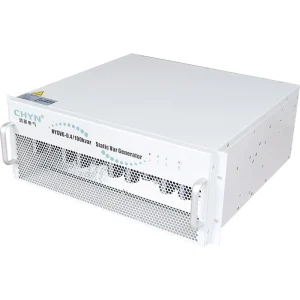
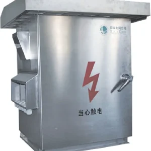
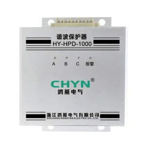
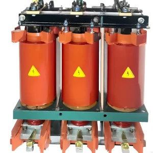
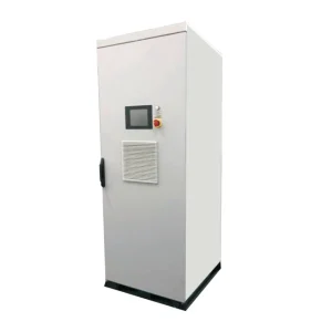
For a conventional closed-loop capacitor-bank controller, the power factor controller CT location normally needs to measure the combined current of the controlled loads and capacitor bank at the selected compensation boundary. Confirm the arrangement in the exact controller drawing before installation. A CT that measures only the capacitor branch, or omits part of the intended load, can give the controller the wrong view of the system. This guide explains how to define that boundary, review alternative supplies and verify the measurement chain. It is an engineering review checklist, not a terminal-by-terminal wiring instruction for an unidentified controller.
Draw the compensation boundary before selecting a conductor
Begin with the approved single-line drawing and mark the point where the required power factor is to be controlled. Trace every load and capacitor branch associated with that point. For the conventional arrangement described here, the sensing point must include their combined effect. Do not choose a convenient cable simply because it is close to the controller enclosure. Physical convenience does not establish that the measured current represents the electrical boundary in the specification.
Create a branch list alongside the drawing. For each branch, state whether it is inside the intended control boundary, whether it can be switched independently and whether it remains visible in each source arrangement. Give the sensing point an identifier that appears on the panel drawings and commissioning sheets. This simple record helps the installer, controller supplier and commissioning engineer discuss the same location without relying on an ambiguous description such as “the main CT.”
Distinguish a valid boundary from a plausible display
A controller can show a believable current magnitude even when the complete measurement arrangement is wrong. Power quantities depend on the relationship between voltage and current, not just the current value. The Analog Devices educational activity on current transformers explains the importance of phase error for power and power-factor measurement. The practical implication is to verify the chain together: physical location, current channel, voltage reference and configured measurement scheme.
Ask the supplier to identify the expected signs and indications under a known operating condition. Record whether the site is importing or exporting active power and how inductive and capacitive reactive power are represented. A negative value should be investigated against the actual operating state before anyone changes polarity or software configuration. In a site with generation, an unexpected sign may reflect real power flow rather than an installation mistake.
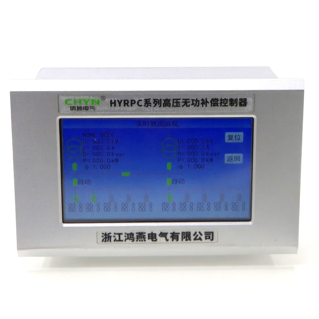
Use the exact controller documentation to settle the connection
Different controllers can use different measurement schemes. The correct phase association, number of CT inputs, voltage reference and parameter setup must come from the supplied model's documentation. A diagram for a visually similar controller is insufficient. Request a controlled drawing with the product identity, revision, input characteristics and terminal designations. If the quotation includes an alternative controller, obtain the corresponding drawing before approving the substitution.
Keep a query register for anything the drawing does not settle. Useful questions include which conductor is measured, what loads are included, how the voltage input is referenced and which parameters must be commissioned. Close each query with a written response tied to the offered equipment. Do not make up a terminal map from general principles or copy another manufacturer's settings. The review should end with one internally consistent set of documents that the installer can actually follow.
Review the location across all permitted source arrangements
A CT position that represents the intended boundary with one incoming supply may not represent it after a bus coupler or transfer arrangement changes. Mark the permitted operating states on separate copies of the single-line drawing. Trace the current paths again rather than assuming that the word “main” has the same meaning in every state. Have the responsible engineer confirm which control arrangement applies to each state.
Do not improvise the combination of independent CT secondaries to solve a multiple-source problem. Request an engineered measurement arrangement appropriate to the controller and system. The resulting proposal should identify any transfer logic, supported summation equipment or operating restrictions it relies on. Where a mode remains unresolved, label it outside the accepted scope until the responsible parties provide a documented solution. This is preferable to commissioning only the easiest supply state and leaving an undisclosed gap.
Turn the review into a traceable checklist
The table below is a qualitative review tool. It does not prescribe CT ratios, accuracy classes, burdens or conductor sizes. Those depend on the actual measurement circuit and equipment requirements. Use the table to collect evidence from the controller supplier and project engineer, then attach the agreed details to the final panel documentation.
| Item | Evidence to retain | What the check establishes |
|---|---|---|
| Physical location | Marked drawing and branch list | The intended load and compensation boundary is measured |
| Phase association | Approved controller measurement diagram | Current inputs correspond to the required voltage references |
| CT and input compatibility | CT identification and controller input data | The selected measurement components are suitable together |
| Source states | Case-by-case path review | The accepted arrangement covers permitted operating modes |
| Commissioning result | Independent readings and controlled step records | The installed chain behaves as intended |
Plan safe verification before touching the secondary circuit
An energized current transformer secondary must not be casually disconnected for a test. California's published rule on current-transformer secondaries prohibits opening the secondary while energized and describes bridging where the primary cannot be deenergized. That jurisdiction-specific rule is a safety reference, not a complete procedure for every site. The work must follow the applicable local requirements and an approved method prepared by competent personnel.
At the planning stage, ask how the circuit will be isolated, tested and restored, and who is responsible for each step. Identify the approved test facilities on the drawing rather than discovering their absence during commissioning. Keep test instruments and procedures within their documented application. This article does not provide an energized rewiring method; the commissioning package should provide the site-specific controls needed before personnel approach the actual equipment.
Verify measurement first, then observe controlled compensation
Under an approved test procedure, compare the controller's measurements with an independent instrument at the same electrical boundary. Record the load state and source arrangement so that the comparison is meaningful. A meter elsewhere in the network may legitimately report different values. If results disagree, resolve the boundary, scaling, phase association and sign conventions before interpreting automatic switching behavior. Otherwise, control adjustments can conceal the original measurement problem.
Once the measurement chain is accepted, observe the response to an authorized capacitor-step change under suitable stable conditions. Record the before-and-after quantities, selected step, delay behavior and status feedback. The aim is to demonstrate the intended closed-loop response, not merely that a relay changes state. If the test conditions cannot support a useful observation, record the limitation and arrange a suitable test rather than declaring the control boundary proven from an inconclusive event.
Specify the enquiry for the CHYN controller being offered
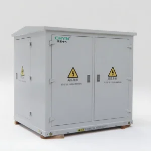
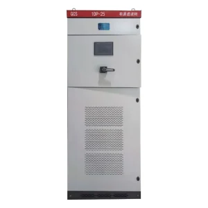
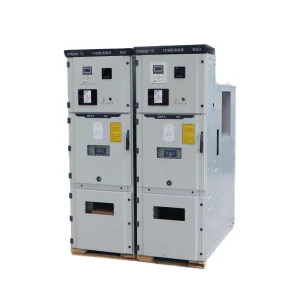
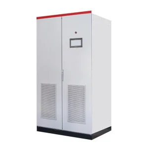
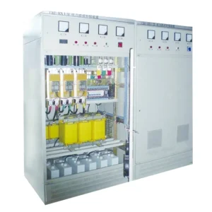
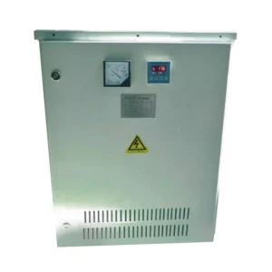
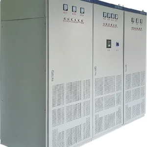
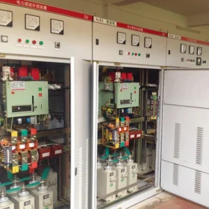
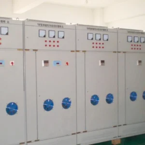
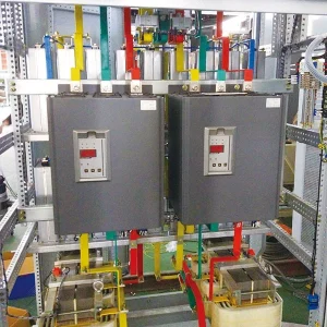
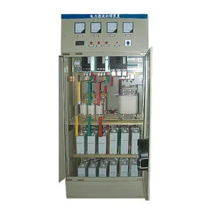
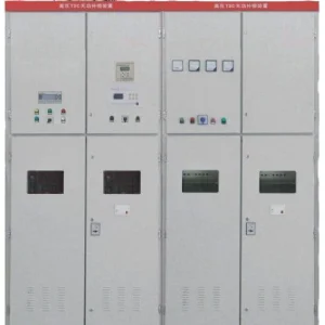
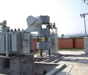
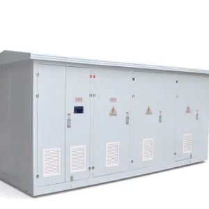
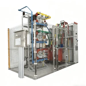
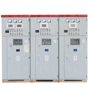
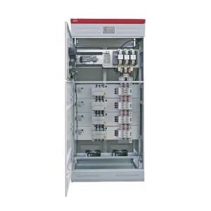
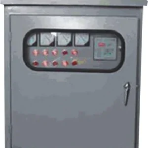
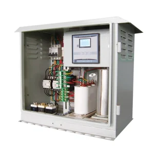
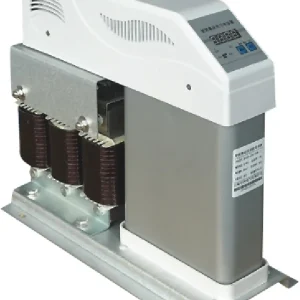
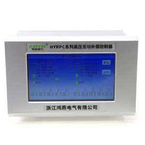
The CHYN HYRPC-130E reactive power compensation controller is the product context for this guide. Send CHYN the single-line drawing, source operating modes, capacitor-bank arrangement and the desired control boundary. Ask for confirmation of the offered measurement scheme, CT requirements and commissioning parameters. The product photograph identifies the controller; it does not prove a particular terminal arrangement, firmware function or suitability for an undocumented multiple-source installation.
For a broader introduction, see what an automatic power factor controller does. If the system switches repeatedly, review APFC panel hunting after the measurements are verified. For sites with generation, the guide to power factor correction with solar PV helps frame the operating cases. These are related decisions, while this article focuses specifically on the measurement boundary.
Keep the accepted sensing point valid after handover
Include the marked drawing, CT identity, controller parameters, commissioning records and unresolved restrictions in the handover package. Give the sensing point a durable identifier that matches the documentation. If a new feeder is connected outside the accepted boundary, the controller cannot be assumed to represent that feeder simply because the rest of the panel remains unchanged. The change should be reviewed before the old acceptance record is reused.
Agree who reviews future changes to supply paths, capacitor steps, controller hardware or voltage references. Require the person making a change to record what was altered and whether the measurement assessment needs repeating. This creates a practical maintenance rule: the accepted arrangement applies to the documented circuit and operating modes. It is not a permanent approval for any later wiring or network configuration that happens to use the same controller enclosure.
Further learning: current and potential transformers
This NPTEL lecture by Prof. Debaprasad Kastha explains instrument-transformer principles. It provides background for understanding the measurement chain. It does not replace the approved controller connection drawing or the site's safe working procedure.
Watch the NPTEL lecture on YouTube.
Frequently asked questions
Should the CT measure only the capacitor-bank current?
For the conventional closed-loop arrangement discussed here, the sensing point should represent the combined load and capacitor effect at the intended control boundary. A capacitor-branch-only measurement does not provide that same information. Confirm the exact scheme and phase association in the documentation for the controller being supplied.
Does a plausible current display prove correct wiring?
No. Current magnitude alone does not verify the relationship between current and voltage used for power calculations. Check the physical boundary, channel assignment, scaling and expected signs against a known operating state. Compare with an independent measurement at the same boundary under the approved commissioning procedure.
Can one CT arrangement cover every transfer-switch state?
Only if the complete measurement scheme has been designed and verified for those states. Trace the current paths separately for each permitted source arrangement and ask the responsible engineer to confirm the solution. Do not improvise connections between independent CT secondaries or assume a normal-source test covers emergency operation.
What must be reviewed when a new feeder is added?
Check whether the feeder falls inside the accepted compensation boundary and whether the controller arrangement still represents the required loads and sources. Update drawings and the branch register, then determine which measurements need repeating. The original acceptance record applies to its documented circuit and operating modes, not automatically to later changes.