
 Zhejiang Hongyan Electric Co., Ltd.





































The capacitor bank symbol in single line diagram is the capacitor mark on a shunt branch, read together with the breaker and any series reactor the drawing includes. Place the breaker ahead of capacitor bank on that branch, and read a series reactor on a one-line only when the sheet draws the coil. The shunt capacitor bank symbol still leaves kvar, wiring, and residual voltage on the equipment record.
Start at the bus and follow power flow before naming the glyph. A plant reader who treats the sheet as a room layout will hunt for a cabinet footprint and miss the branch order.
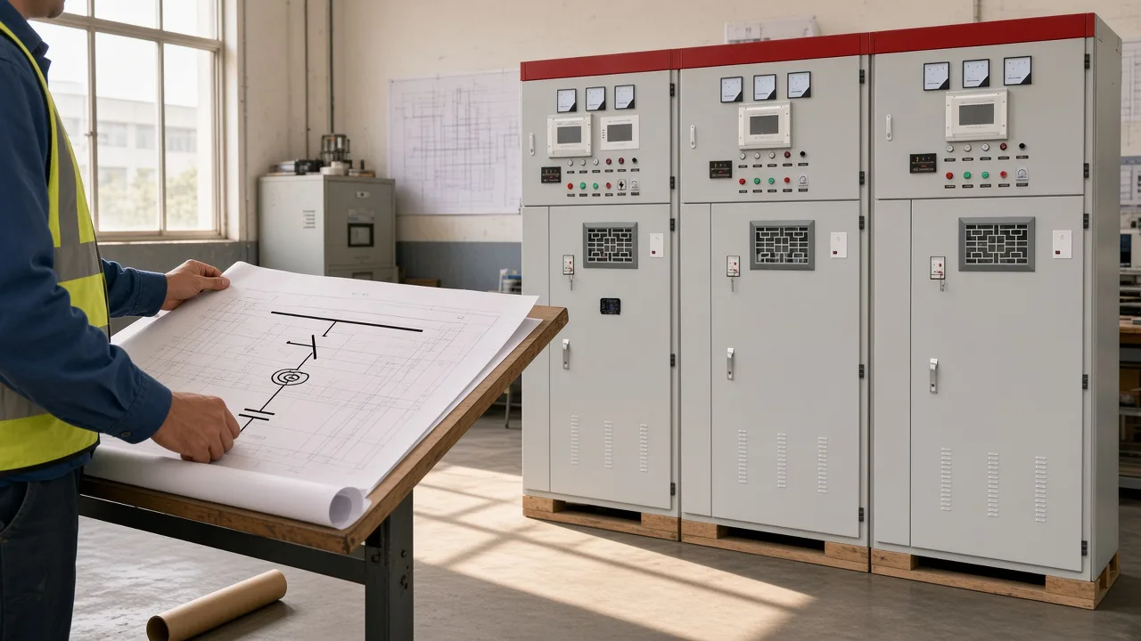
Hold the covered-nameplate cabinet beside the sheet and match the branch, not the door count. The next sections walk that branch in order, then say which ratings stay off the ink.
Use this list to jump to the breaker, the reactor, or the cabinet match.
- What a single-line diagram is showing
- How to read the capacitor symbol
- Where the breaker sits on the bank branch
- What a series reactor means when it is drawn
- What the symbol does not decide
- Which HYTBB cabinet fits this shunt-bank symbol
What a single-line diagram is showing
A single-line diagram uses one line for a multi-conductor circuit and shows electrical connection, not physical placement. In plain language, the drawing shows how power is connected, not where the gear sits in the room.
A heavier horizontal line is the bus, sometimes called a busbar. Follow that bus before you look for a shunt branch leaving it.
A diagram-software guide describes a one-line as the power path from the incoming source to each downstream load. An educational transcript on single-line reading uses five steps: drawing structure with the bill of materials and title block, equipment function, the symbols printed on that sheet, bus arrangement, then incoming and outgoing power flow.
How to read the capacitor symbol
The usual capacitor symbol is two parallel lines, and the branch notes plus the grouped units tell you the mark is a shunt capacitor bank. A curved plate is a different electronics mark, covered below, and it is not the default plant shunt mark.
SparkFun capacitor symbols describe two common schematic drawings: two parallel lines, flat or curved. On that tutorial the curved line indicates a polarized capacitor symbol, meaning the part is probably an electrolytic symbol.
An exam-prep note on single-line diagrams says a capacitor is represented by two parallel lines and is often used for power-factor correction.
A single-line symbol library lists a capacitor stencil beside a circuit breaker, a reactor, and a current transformer. The library names the marks and still leaves the reading order to the sheet in front of you.
Capacitor banks: characteristics and applications defines a shunt capacitor bank as a set of capacitor units in a parallel and series association inside a steel enclosure. One component mark, with no bank note and no grouped units, is a lone capacitor until the branch says otherwise.
From the field: Two parallel lines can be misread as a contact, so the legend or the class letter has to settle the mark — KiCad capacitor-symbol thread.
After the legend settles the glyph, read the branch from the bus downward. The sheet in the next figure puts the breaker, the coil, and the capacitor mark in that order.
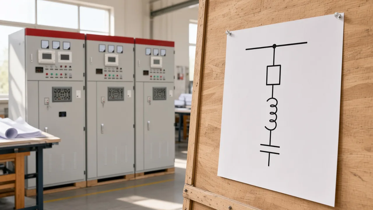
Match the ink to the branch, then look for a note that prints voltage or kvar beside the bank. A published utility one-line prints 3x48 MVAR, 121 kV, and 115 kV beside the capacitor bank.
| Reading step | What to look for | What it tells you |
|---|---|---|
| Bus | Heavier horizontal line | Where the branch leaves |
| Breaker or switcher | Device ahead of the capacitors | What connects the bank |
| Series reactor if drawn | Coil on that branch | Inrush or detuning duty is on the sheet |
| Capacitor symbol | Two parallel lines | The shunt bank mark |
| Note beside the symbol | kvar, voltage, or reactor percent | Ratings the glyph leaves to text |
Where the breaker sits on the bank branch
Read the breaker or switcher on the bank branch before you treat the capacitor mark as the whole installation. The circuit breaker is the switch that connects and disconnects that branch.
One published substation one-line, in the IEEE Fort Worth PES shunt-capacitor presentation, places a circuit breaker or switcher and a current-limiting reactor beside the shunt capacitor bank, with 345 kV lines on a north bus and a south bus. The same presentation names IEEE Std 1036 and C37.99 as guide titles on the standards slide.
Substation technicians describe the chain as a breaker, then a vacuum switch, then the capacitor bank, sometimes with series inrush reactors for each vacuum breaker. The report is about switching order on a substation bank.
Look for the breaker ahead of capacitor bank even when the label says switcher instead of breaker. Fixed, manual, or automatic group switching is a cabinet configuration, and the one-line may show only the device that closes the branch.
What a series reactor means when it is drawn
A series reactor, when the drawing includes one, sits in series with the bank, and that coil is where a reactor note belongs. In plain language, it is the coil that limits inrush or detunes the bank when the sheet shows it.
From the field: Read a reactor only when the drawing shows it, as a current-limiting reactor on the chapter one-line or a damping reactor between the bank and the common bus — IEEE Fort Worth PES shunt-capacitor presentation.
In Swedish TSO TR01-17E, the damping reactor is drawn between each phase of the capacitor bank and the common bus, and the guideline's own rated frequency is 50 Hz. Rated inductance in that guideline is selected from 0.25 mH, 0.5 mH, 1.0 mH, 1.5 mH, and further 0.5 mH steps, and the guideline's service altitude is under 1000 m.
Those inductance steps, that altitude, and that 50 Hz line belong to the guideline. Series reactors for the HYTBB cabinet are described as typically 4.5–6% for 6 kV systems and 12–13% for 10 kV systems.
The percent lives in the equipment note, not inside the two parallel lines. For why the reactor is used, see why a reactor is used in a capacitor bank, and keep the discussion on where the coil sits.
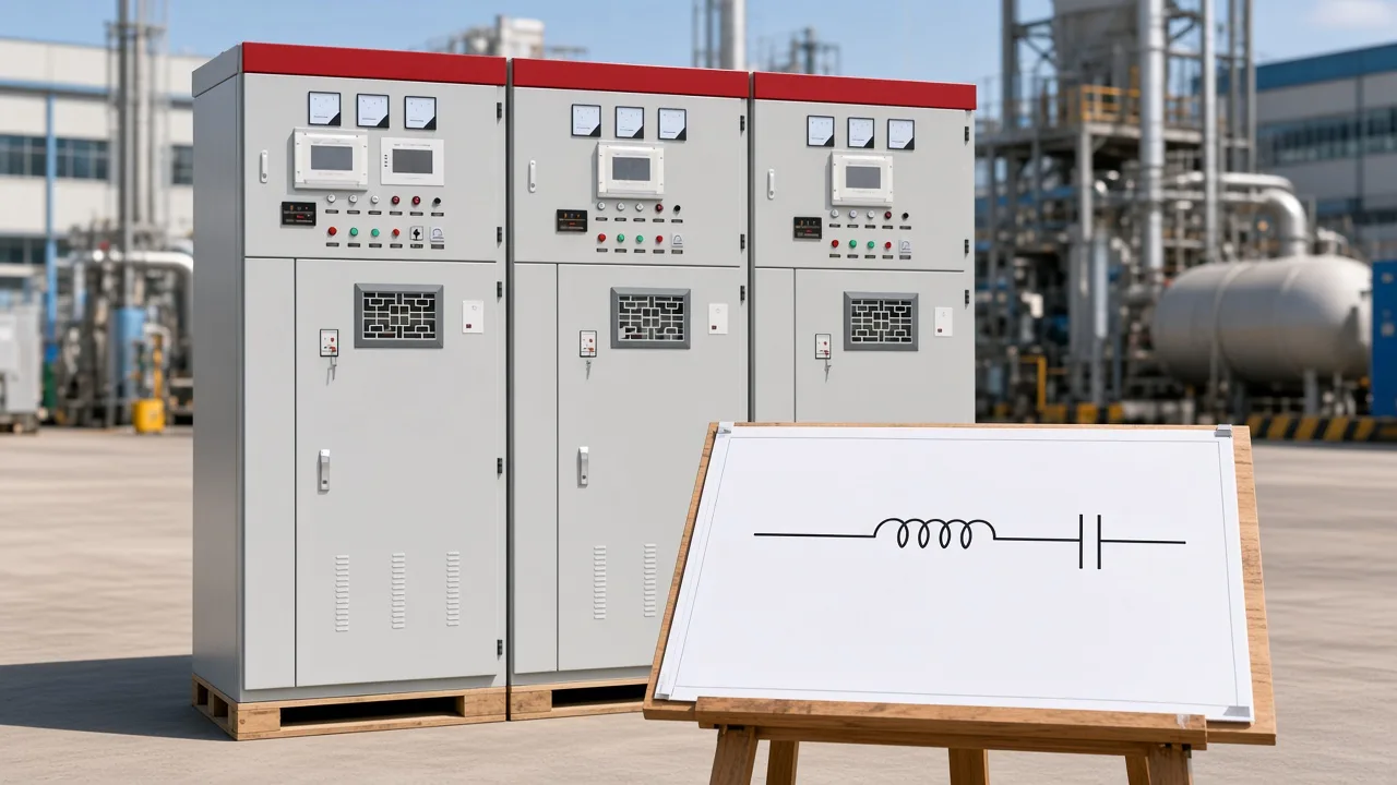
If the branch has no coil, the sheet is not claiming a series reactor on a one-line. Add the reactor only when a later revision draws it, and write the percent in the note.
What the symbol does not decide
The symbol leaves delta versus wye, an active-filter drawing, and the kvar note to other records. Two parallel lines do not choose the connection, and they do not draw a filter.
Delta and wye wiring, including a star connection, is the job of capacitor bank wiring. An active harmonic filter diagram is a different drawing, covered in active harmonic filter diagram.
A PCB assembly guide says ANSI/IEEE 315 draws a non-polarized capacitor as two parallel lines and IEC 60617 draws it as two parallel rectangles, and that the symbol does not state the chemistry. Capacitance in farads on an electronics schematic is a different mark from a kvar bank note.
Inside the cabinet, a discharge resistor and a current transformer may still be absent from the ink. A discharge circuit and a CT support protection and metering, which shunt capacitor bank fundamentals and protection treats as protection practice rather than as glyph shape.
Banks may keep a charge after power is removed, which is why a discharge resistor is listed with the equipment. The one-line can omit that part and still be a valid connection diagram.
Which HYTBB cabinet fits this shunt-bank symbol
HYTBB can be the shunt cabinet this symbol stands for when the project uses that model, and the glyph still leaves the ratings to the cabinet record. The HYTBB medium and high voltage reactive power compensation cabinet functions as a shunt capacitor bank that compensates for inductive reactive power.
That job is power-factor correction, also called reactive power compensation, for industrial and distribution readers who already have a one-line. Open the high-voltage power factor compensation series if the branch is a different device in that family.
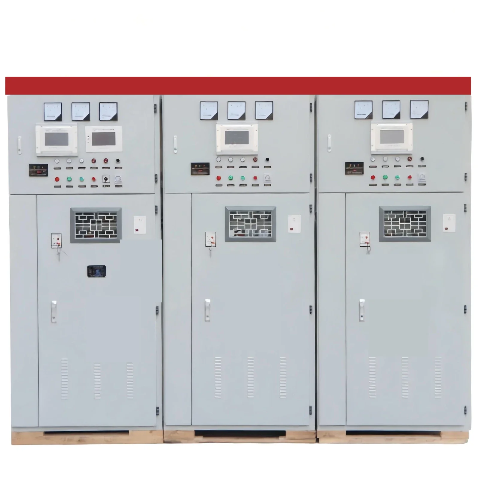
Match this photograph to the shunt branch only. An overview sentence, kept apart from the parameter table, places HYTBB on systems from 1 kV to 35 kV.
Rated voltage in the parameter table is 10(6)–35 kV. Rated frequency in that table is 50 Hz.
Rated capacity in that table spans 50–20,000 kvar. Neutral connection in that table is isolated neutral or non-effective grounding.
From the field: Keep the overview span of 1 kV to 35 kV apart from the parameter-table voltage 10(6)–35 kV, and read this cabinet at 50 Hz — HYTBB cabinet record.
Performance features say residual voltage drops below 50 V within three minutes after disconnection, and the working-principle line says discharge resistors bring residual voltage below 50 V within five minutes. Quote both lines together when residual voltage is part of the match.
HYTBB is described as able to reach a power factor of 0.95 or higher and to reduce line current by 10–20%. Long-term operation is printed at 1.0 times rated voltage, with a short-duration withstand up to 1.3 times rated voltage.
Operating limits print ambient from −40°C to +45°C, relative humidity at or below 90% at 25°C, and altitude at or below 4500 m. The parts list includes high-voltage parallel capacitors, reactors, vacuum circuit breakers, current transformers, discharge resistors, and control and protection units.
Switching may be fixed, manual, or automatic group switching, and the cabinet may run alone or be combined with KYN28 or KYN61 switchgear. Listing files, test reports, and the reactor percent stay with the cabinet record.
| Record item | Printed wording | How to keep it |
|---|---|---|
| Overview voltage | 1 kV to 35 kV | Separate from the table row |
| Parameter-table voltage | 10(6)–35 kV | Table row only |
| Rated frequency | 50 Hz | Cabinet table only |
| Rated capacity | 50–20,000 kvar | Table row |
| Neutral connection | Isolated neutral or non-effective grounding | Table wording |
| Residual voltage | Below 50 V within three minutes, and below 50 V within five minutes | Keep both lines |
FAQ
What is the capacitor bank symbol on a single-line diagram?
It is the capacitor mark on the shunt branch, commonly two parallel lines, read with the breaker and any series reactor the sheet includes. A curved plate on an electronics schematic is the polarized form in the SparkFun tutorial, not the default plant bank mark.
How do you recognize a shunt capacitor bank on a plant one-line?
Look for a branch that leaves the bus, a breaker or switcher, a coil only if it is drawn, and a capacitor mark with a bank note or grouped units. The HYTBB cabinet is one shunt cabinet that mark can stand for when the project uses that model.
Where is the breaker drawn relative to the capacitor bank?
Read the breaker or switcher on the branch ahead of the capacitors. Field language also describes a breaker, then a vacuum switch, then the bank, sometimes with series inrush reactors.
What does a series reactor mean if it is drawn with the bank?
The coil is in series with the bank for inrush limiting or detuning, and the percent belongs in the note. On the transmission example, the damping reactor sits between each capacitor phase and the common bus.
Does the symbol show whether the bank is delta or wye?
The glyph leaves the connection to the wiring note or the equipment record. Neutral connection for the HYTBB cabinet is printed as isolated neutral or non-effective grounding, which is a table row rather than a feature of the two lines.
What does the symbol leave off the drawing?
The mark can omit the discharge resistor, the current transformer, the control unit, and both residual-voltage lines. Physical door layout and nameplate text are also outside the ink.
Which frequency does the HYTBB cabinet print?
Rated frequency printed for the HYTBB cabinet is 50 Hz. Keep that table row separate from the 50 Hz line in the Swedish transmission guideline.